 (1)_1794907655_WNo_1000d563.webp)
Table of Contents
- What Is a Magnetic Coupling?
- How Does a Magnetic Coupling Work?
- What Are the Main Types of Magnetic Couplings?
- What Are the Key Components of a Magnetic Coupling?
- What Are the Advantages of Magnetic Couplings?
- Where Are Magnetic Couplings Used?
- FAQ
- Conclusion
What Is a Magnetic Coupling?
A magnetic coupling is a mechanical power transmission device that uses magnetic forces to transfer torque between two rotating components without requiring them to touch directly. Think about holding two magnets on opposite sides of a sheet of paper. Even though the magnets cannot physically touch, you can still feel them attracting or repelling each other. A magnetic coupling works in a similar way, but with carefully arranged magnets and rotating assemblies. Unlike an ordinary permanent magnet, which is mainly used to attract, hold, or repel objects, a magnetic coupling is specifically engineered to transfer rotational motion and torque from a driving shaft to a driven shaft. In many industrial designs, the two rotating assemblies are separated by an air gap or a non-magnetic containment shell, allowing power to pass through without a direct mechanical connection.
Main Structure of a Magnetic Coupling
- Driving Rotor (Outer Rotor)
- Driven Rotor (Inner Rotor)
- Permanent Magnets
- Containment Shell or Air Gap
- Drive Shaft
- Driven Shaft
- Magnetic Back Iron
Key Characteristics of Magnetic Couplings
- Contactless torque transmission
- No direct mechanical connection between the two rotors
- Reduced contact-related mechanical wear
- Potential for hermetically sealed equipment designs
- Magnetic overload protection in suitable designs
Common Applications of Magnetic Couplings
- Chemical Processing Industry
- Pharmaceutical and Biotechnology Industry
- Food and Beverage Processing
- Industrial Pump and Fluid Handling Systems
- Industrial Mixing and Agitation Equipment
How Does a Magnetic Coupling Work?
So, how does a magnetic coupling actually transfer power without two shafts being physically connected? The secret is the interaction between magnetic fields. In a typical permanent magnet coupling, one group of magnets is installed in the driving rotor, while another group is installed in the driven rotor. When the driving rotor starts turning, its magnetic field interacts with the magnetic field of the driven rotor, causing the second rotor to follow. It's a little like two people holding opposite ends of a rope: when one person pulls, the other person feels the force and moves along. The difference is that a magnetic coupling transfers this force through a magnetic field instead of a physical rope.
Magnetic Coupling Working Principle
The following diagram shows how a typical synchronous permanent magnet coupling transfers rotational motion from the driving side to the driven side.
Now, let's break the working process down into four simple steps.
Step 1: The Driving Rotor Starts Rotating
First, an electric motor or another power source turns the driving shaft, which is connected to the driving rotor. Permanent magnets mounted inside this rotor begin rotating with it. You can think of this as turning the handle of a hand-operated machine: once the handle moves, it provides the initial motion needed to operate the rest of the system. At this stage, the driving rotor creates a rotating magnetic field around the coupling.
Step 2: Magnetic Fields Interact Across the Gap
Next, the magnetic field produced by the driving rotor interacts with the magnets on the driven rotor. Opposite magnetic poles attract, while like poles repel, creating magnetic forces that act on the second rotor. The two assemblies don't need to touch because the magnetic field can cross the space between them. In sealed equipment, this field can also pass through a suitably designed non-magnetic containment shell.
Step 3: The Driven Rotor Follows the Driving Rotor
As the driving rotor continues turning, the magnetic interaction creates torque on the driven rotor. The driven rotor starts rotating and transfers this motion to its connected shaft and equipment. In a properly designed synchronous coupling operating below its pull-out torque, both rotors maintain the same average rotational speed. It's similar to two dancers keeping the same rhythm: one leads, and the other follows without needing to hold hands.
Step 4: Rotational Power Reaches the Equipment
Finally, the driven shaft delivers mechanical power to the connected equipment, such as a pump impeller or an industrial mixer. The entire process happens without a direct mechanical connection between the two magnetic rotors. However, this doesn't mean the coupling can transmit unlimited torque. If the load becomes too high, the magnetic connection may lose synchronism, causing the driving rotor to continue turning while the driven rotor slows down or stops.
What Are the Main Types of Magnetic Couplings?
Not every magnetic coupling works in exactly the same way. Some use permanent magnets to keep two rotating assemblies synchronized, while others rely on induced electrical currents or magnetic hysteresis to transmit torque. Let's look at three common operating principles and where each one makes the most sense.
1. Permanent Magnet Synchronous Coupling
A permanent magnet synchronous coupling uses permanent magnets on both rotating assemblies to transmit torque through magnetic attraction and repulsion.
Characteristics:
- Maintains a fixed average speed ratio of 1:1 in a standard coaxial synchronous design.
- Can transmit torque through a sealed, non-magnetic containment barrier.
- Provides magnetic overload protection through controlled loss of synchronism in suitable designs.
- Does not require an external electrical supply to energize its permanent magnets.
Working Principle:
Permanent magnets are arranged on the inner and outer rotors with alternating magnetic poles. When the driving rotor turns, the magnetic fields interact and produce torque that makes the driven rotor follow. As long as the applied load stays below the coupling's pull-out torque, both rotors remain synchronized.
Common Applications:
- Magnetic drive centrifugal pumps
- Chemical transfer pumps
- Hermetically sealed pump systems
- Pharmaceutical processing equipment
- Sealed industrial mixers and agitators
2. Eddy Current Magnetic Coupling
An eddy current coupling works differently from a synchronous permanent magnet coupling. Instead of relying on two sets of permanent magnets locking together, it uses a rotating magnetic field to induce electrical currents in a conductive component.
Characteristics:
- Allows controlled speed difference between the input and output shafts.
- Can provide soft starting and adjustable-speed operation in suitable systems.
- Does not require the two rotating components to maintain a fixed synchronous speed relationship.
- Can provide smooth torque transmission under varying load conditions.
Working Principle:
When the magnetic rotor spins, its changing magnetic field passes through a nearby conductive rotor or drum. This induces eddy currents in the conductive material, and those currents create their own magnetic field. The interaction between the two fields produces torque, allowing the output rotor to turn. A speed difference is normally needed to induce the currents and transfer torque.
Common Applications:
- Industrial speed-control drives
- Conveyor systems
- Large fans and blowers
- Industrial test benches
- Variable-speed machinery
3. Hysteresis Magnetic Coupling
A hysteresis coupling uses a permanent magnet assembly and a special magnetic material that responds to changes in the applied magnetic field. It is particularly useful when smooth torque transmission and controlled slip are more important than keeping both shafts at exactly the same speed.
Characteristics:
- Can produce relatively constant torque over a range of slip speeds within its design limits.
- Provides smooth engagement without the same rigid magnetic locking behavior as synchronous couplings.
- Can be useful for tension control and applications requiring controlled torque.
Working Principle:
The permanent magnet assembly creates a rotating magnetic field around a hysteresis material. As the field changes, the material undergoes repeated magnetization and produces a resisting torque. This torque drives the output component, while a speed difference may remain between the input and output sides.
Common Applications:
- Wire and cable winding machines
- Film and paper winding equipment
- Printing machinery
- Precision tension-control systems
- Laboratory torque-control equipment
What Are the Key Components of a Magnetic Coupling?
Now that we've looked at how a magnetic coupling works, let's take a closer look at what's inside. Think of it like opening up a mechanical watch. Every small component has a specific job, and if one part is poorly designed, the whole system may not work as expected. A typical permanent magnet drive coupling contains several key components, although the exact arrangement depends on the application.
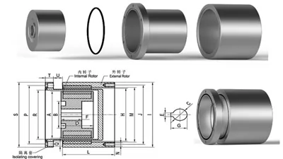
Magnetic Coupling Structure Diagram
1. Driving Rotor
Function: The driving rotor receives rotational power from the motor or input shaft and carries the driving-side magnetic assembly. It creates the rotating magnetic field that transfers torque to the other rotor.
Design Benefit: A properly designed rotor keeps the magnets securely positioned and helps maintain consistent magnetic performance during rotation.
2. Driven Rotor
Function: The driven rotor responds to the magnetic field generated by the driving rotor. It transfers the resulting torque to the output shaft, pump impeller, or connected equipment.
Design Benefit: Its magnetic arrangement and mechanical dimensions are matched to the driving rotor to achieve the required torque and operating speed.
3. Permanent Magnets
Function: Permanent magnets generate the magnetic fields needed to transmit torque between the two rotors. Common choices include neodymium iron boron (NdFeB) and samarium cobalt (SmCo), depending on the required magnetic strength and operating temperature.
Design Benefit: High-performance magnet materials can provide strong magnetic fields in a relatively compact assembly, helping manufacturers achieve the required torque within limited installation space.
4. Containment Shell
Function: In a sealed magnetic drive pump, the containment shell separates the process fluid from the motor-side assembly while allowing the magnetic field to pass through. It also acts as a pressure boundary and must be designed for the system's operating conditions.
Design Benefit: It makes hermetically sealed drive arrangements possible without a conventional rotating shaft penetration through the pressure boundary. Material selection is important because conductive metal shells can generate eddy-current heat.
5. Magnetic Back Iron
Function: Magnetic back iron provides a low-reluctance return path for magnetic flux and helps direct the magnetic field through the intended coupling region. It is commonly positioned behind the permanent magnets.
Design Benefit: A properly designed magnetic circuit can improve useful magnetic flux and reduce unnecessary leakage, helping the coupling reach its target torque performance.
6. Drive Shaft and Driven Shaft
Function: The drive shaft connects the input power source to the driving rotor, while the driven shaft transfers the output torque to the machine. They form the mechanical interfaces between the coupling and the rest of the equipment.
Design Benefit: Correct shaft dimensions, keyways, splines, and alignment help prevent installation problems, unwanted vibration, and excessive mechanical stress.
What Are the Advantages of Magnetic Couplings?
Why would an engineer choose a magnetic coupling instead of a conventional mechanical one? The answer usually comes down to how the equipment needs to operate. Here are some of the most important advantages.
1. Contactless Torque Transmission
One of the biggest benefits is that the two magnetic rotors can transfer torque without direct mechanical contact. This removes the need for a physical connection between the rotating components and makes magnetic couplings particularly useful in isolated drive systems.
2. Reduced Mechanical Wear
Because the magnetic torque transmission itself does not depend on two coupling halves rubbing against each other, contact-related wear at that interface is reduced. However, bearings, support components, and other mechanical parts may still require routine maintenance.
3. Support for Leak-Resistant Equipment Design
When used with a properly engineered containment shell, a magnetic coupling can eliminate the rotating shaft penetration found in many conventional pump arrangements. This is particularly valuable when handling hazardous, corrosive, toxic, or expensive fluids. The actual leakage protection still depends on the complete equipment design and static sealing arrangement.
4. Magnetic Overload Protection
Some synchronous magnetic couplings can slip or lose synchronism when the applied torque exceeds their pull-out limit. This can help prevent excessive torque from being transmitted to downstream components, although the resulting loss of drive can also interrupt the process and requires prompt attention.
5. Greater Design Flexibility
Magnetic couplings can be customized according to shaft dimensions, torque requirements, magnet materials, operating temperatures, and installation space. This gives equipment manufacturers more freedom when developing specialized pumps, mixers, and other industrial machines.
Where Are Magnetic Couplings Used?
Magnetic couplings are especially useful when equipment needs to transfer rotational power while keeping two mechanical sections separated. You'll often find them in applications where leakage, contamination, or mechanical contact could create operational problems. Let's look at a few practical examples.
1. Chemical Processing Equipment
Chemical plants often handle corrosive liquids, solvents, and other substances that must not escape into the surrounding environment. Magnetic drive pumps use a magnetic coupling and containment shell to transfer power without a rotating shaft passing directly through the pressure boundary. This makes them useful for handling certain hazardous or aggressive fluids, provided the materials and pressure ratings match the process.
2. Pharmaceutical and Biotechnology Equipment
In pharmaceutical production, contamination control is a major concern. Magnetic drive arrangements can help isolate the motor and drive components from the process side. They are used in selected pumps and mixing systems where the design must support controlled processing and suitable cleaning requirements.
3. Food and Beverage Processing
Food production equipment often needs to keep lubricants, dust, and other external contaminants away from the product. Magnetic coupling arrangements can help separate the drive system from the process fluid. However, the materials, surface finish, cleaning method, and hygienic design must all meet the specific requirements of the application.
4. Industrial Pumps and Fluid Handling Systems
This is one of the most familiar applications of magnetic couplings. A magnetic drive pump uses the outer rotor to transfer torque magnetically to the inner rotor, which drives the impeller. The arrangement can eliminate a conventional dynamic shaft seal, making it attractive for certain fluid transfer systems.
5. Industrial Mixers and Agitators
Some mixing tanks and reactors use magnetic couplings to transfer rotational motion into a sealed vessel. Instead of running a rotating shaft through the vessel wall, the magnetic assembly transmits torque across a stationary barrier. This can be useful in applications where maintaining a sealed processing environment is important.
Frequently Asked Questions
1. How does a magnetic coupling transmit torque without physical contact?
A magnetic coupling transmits torque through the interaction of magnetic fields generated by its driving and driven assemblies. When the driving rotor turns, its magnetic poles create forces that act on the driven rotor's magnets, causing the second rotor to follow. In a typical synchronous design, both rotors maintain the same average speed when the load stays below the pull-out torque. There is no need for the two rotors to physically touch, although bearings and shafts still provide mechanical support.
2. What happens if a magnetic coupling is overloaded?
When the required torque exceeds the coupling's pull-out torque, a synchronous magnetic coupling can lose synchronism. In a magnetic drive pump, the motor-side rotor may continue spinning while the impeller-side rotor slows down or stops. This can produce abnormal noise, vibration, and heat. Stop the equipment promptly, check for blocked discharge lines, seized bearings, impeller obstruction, excessive starting torque, or other causes of overload, and do not restart until the problem has been identified and corrected.
3. How much torque can a magnetic coupling transmit?
There is no single torque limit for all magnetic couplings. Capacity depends on rotor diameter, magnet grade, pole arrangement, air gap, containment shell thickness, operating temperature, and rotational speed. For example, a coupling rated for 10 N·m cannot automatically replace one rated for 100 N·m, even if their external dimensions look similar. When selecting a unit, provide the continuous operating torque, peak torque, startup load, and maximum speed to the manufacturer. If you know motor power and speed, a useful starting formula is T (N·m) = 9550 × P (kW) ÷ n (rpm).
4. What is the role of the air gap in a magnetic coupling?
The air gap separates the driving and driven magnetic assemblies and allows the magnetic field to interact across the distance. Increasing this gap generally reduces magnetic coupling strength and available torque, although the exact relationship depends on the magnetic circuit. In a sealed pump, the containment shell also contributes to the effective magnetic separation. Always use the manufacturer's specified rotor clearance and shell dimensions rather than reducing the gap without checking mechanical tolerances, deflection, and thermal expansion.
5. Can a magnetic coupling work through a stainless steel containment shell?
Yes, a magnetic coupling can work through a suitably designed non-magnetic austenitic stainless steel shell, such as certain grades of 304 or 316 stainless steel. However, stainless steel is not automatically non-magnetic in every condition, and cold working can change its magnetic response. In addition, a conductive metal shell can develop eddy currents and generate heat during operation. The shell material, wall thickness, pressure rating, and thermal performance should therefore be checked together with the magnetic circuit before finalizing the design.
Conclusion
So, how does a magnetic coupling work? In simple terms, it uses magnetic fields to transfer rotational torque from one rotor to another without requiring a direct mechanical connection. By carefully arranging permanent magnets or using other magnetic operating principles, a coupling can transfer power while reducing contact-related wear and supporting sealed equipment designs. Whether you're working with a chemical pump, an industrial mixer, or a specialized piece of machinery, the key is to match the coupling's torque capacity, magnet material, air gap, temperature rating, and structure to the actual operating conditions.
If you're looking for a magnetic coupling for an industrial project, it's worth choosing a supplier that can do more than provide a standard magnetic assembly. FZMAG (Faizeal Magnetic Technology) specializes in permanent neodymium magnetic drive couplings, magnetic rotors, laminated magnets, and customized magnetic assemblies. Whether you need a specific shaft configuration, a customized magnetic circuit, or an OEM/ODM magnetic coupling solution, you can explore its products and manufacturing capabilities to find a suitable starting point. Have a drawing, technical specification, or application requirement ready? Contact the FZMAG team to discuss your project and request a customized quotation.