
+86-574-87520996
sales@fzmag.com
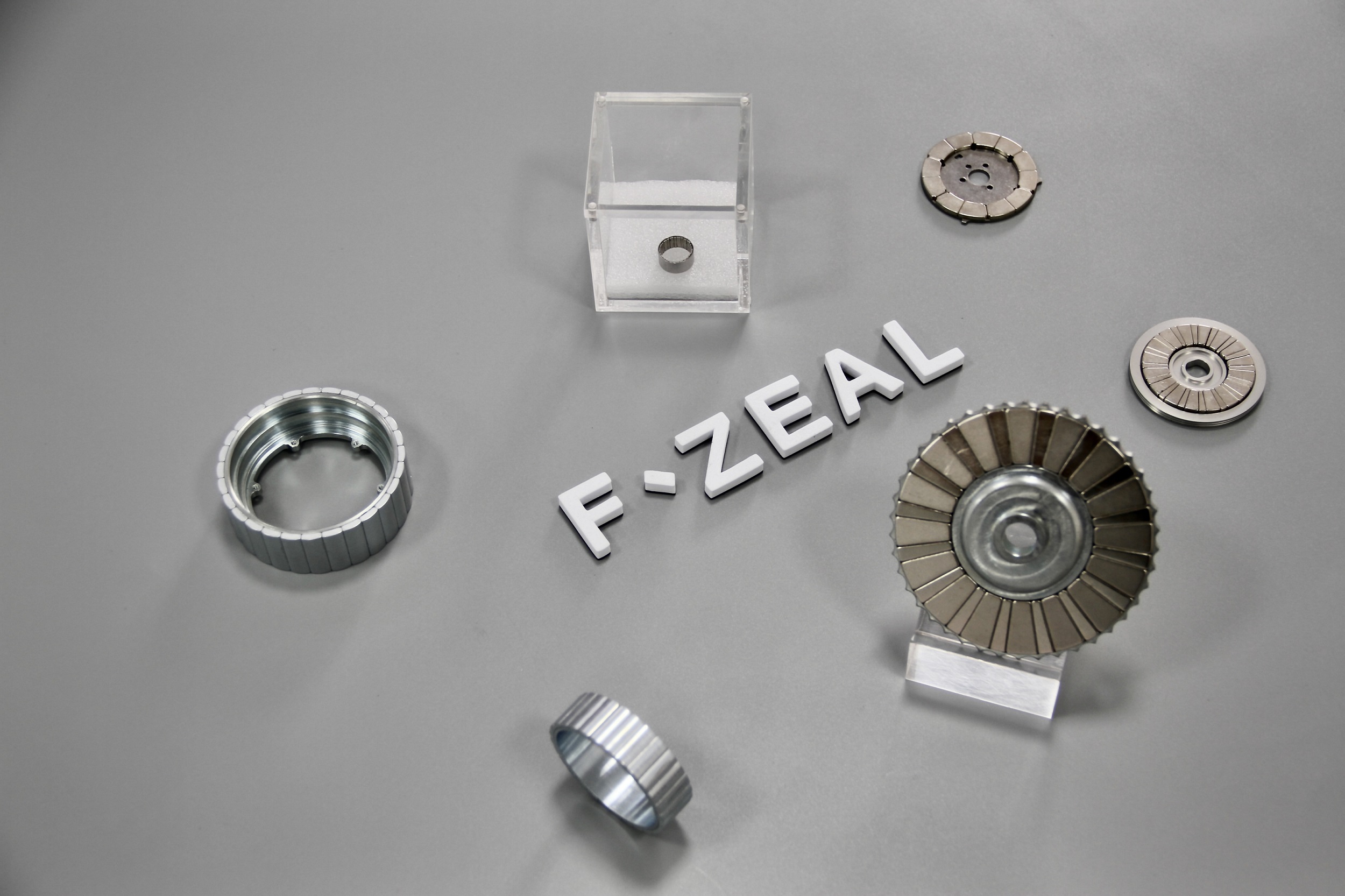
Sintered NdFeB is the preferred magnetic material for high-torque-density knee and shoulder joint motors.
| Parameter | Sintered NdFeB | Bonded NdFeB | SmCo | Ferrite |
|---|---|---|---|---|
| Remanence Br (T) | 1.05–1.45 | ~1/3–1/4 of sintered | Lower than NdFeB | Far below NdFeB |
| Max energy product (kJ/m³) | 240–474 | ~1/3–1/4 of sintered | Lower than NdFeB | Far below NdFeB |
| Max operating temp (°C) | 80–240 (UH/EH) | 120–150 | 250–350 | >200 |
| Corrosion resistance | Requires coating (Ni/Zn/Epoxy) | Good | Excellent | Excellent |
| Cost | High | Medium | Very high (cobalt scarcity) | Low |
| Best for | Knee, shoulder, finger joints | Encoder wheels, small finger joints | Aerospace / specialized high-temp | Cost-sensitive, low-speed, low-power torque motors |
Conclusion: high-torque-density knee and shoulder joints must use sintered NdFeB. For finger joints where extreme volume compression is required, sintered NdFeB also delivers the best performance-to-size ratio.
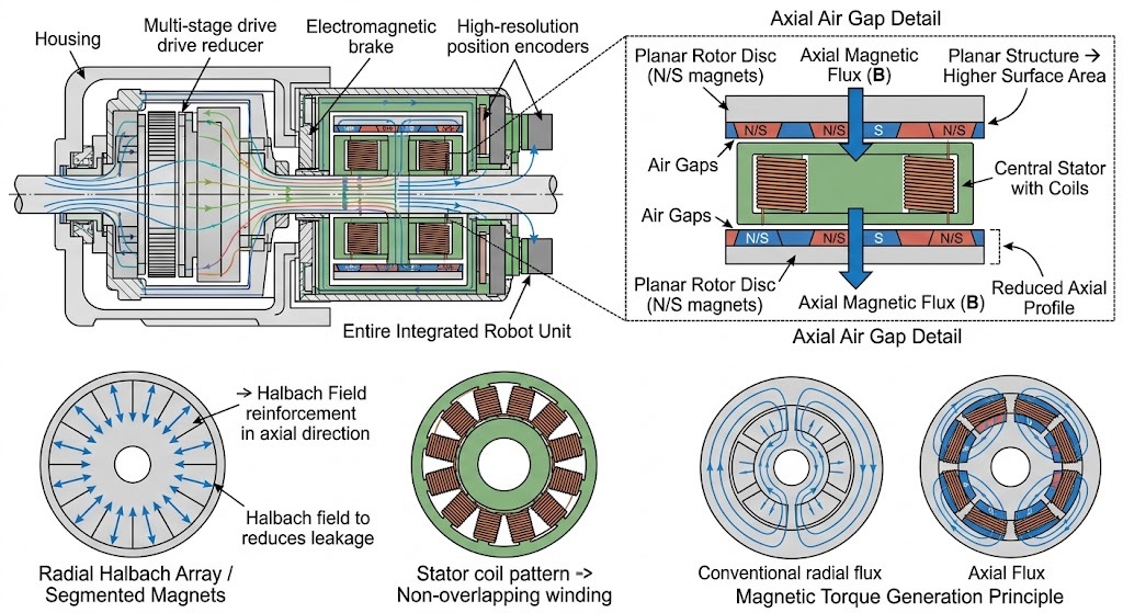
A conventional radial multi-pole rotor consists of alternating N-pole and S-pole fan-shaped magnet segments. Magnetic flux exits the N pole, crosses the air gap into the stator teeth, returns through the stator yoke to the adjacent S pole, then back through the rotor back-iron to the next N pole.
Where: Br = magnet remanence (T); μ0 = permeability of free space (4π×10⁻⁷ H/m); kσ = leakage coefficient (1.1–1.4); lg = air gap length (m); μr = relative recoil permeability of the magnet (1.02–1.05); g = πD/2p = ratio of mean air gap circumference to pole pitch (D = rotor outer diameter, p = pole pairs).
Design practice sets air gap length typically at 0.5–1.2 mm. Leakage coefficient typically ranges from 1.1–1.4. Peak air gap flux density in conventional radial rotors is typically 0.8–1.2 T.
Halbach (1979) demonstrated that arranging magnet segments with progressively rotating magnetization directions concentrates flux on one side while suppressing it on the other.
Where: t = magnet ring wall thickness (m); k = π / (D_avg × ln(D_o/D_i)); D_o and D_i = rotor outer and inner diameters (m); p = number of pole pairs.
Compared with a conventional radial configuration, an ideal Halbach array increases single-sided air gap flux density by 30% to 60%, with virtually no stray flux on the passive side. This allows the stator yoke to be eliminated or thinned, reducing overall motor weight.
Continuous Halbach magnetization must be discretized into multiple fan-shaped segments for practical manufacturing. A typical implementation uses 4 or 6 segments per pole, each with a magnetization direction rotated by a fixed angle (180°/n). Common engineering choices are 4 segments per pole (45° rotation) or 6 segments per pole (30° rotation).
Halbach arc segment fixation after assembly is critical for reliability. FAIZEAL implements a dual-protection approach combining physical fixation with adhesive bonding.
Machine a dovetail or rectangular groove at the bottom of each arc segment, press-fit into a matching groove in the steel back-iron, retain axially with end caps, and fix radially through interference fit.
Where: m = mass of a single arc segment (kg); ω = angular velocity (rad/s), ω = 2π × n / 60 with n = maximum speed (rpm); r_avg = centroid radius of the arc segment (m); σ_allowable = material yield strength (MPa); A_contact = groove contact area (m²). For Grade 10 steel with yield strength 205 MPa, a safety factor ≥ 3 is required.
The steel shaft sleeve outer diameter is pressed into the inner bore of the back-iron with interference fit (recommended fit class H7/u6 or H7/s6). Material elasticity clamps the arc segments tight against centrifugal and vibration forces without any adhesive.
Where D_inner is the back-iron inner bore diameter (mm).
Install plastic end rings on both sides of the rotor to constrain axial movement of the magnet segments, while providing assembly guidance and edge chip protection.
On top of the physical fixation methods above, apply a structural epoxy (such as Loctite E-120HP or equivalent high-temperature epoxy) at the interface between each arc segment and the back-iron. After curing, the adhesive layer delivers shear strength of 15 to 30 MPa, absorbs micro-vibrations, and fills residual gaps.
Where: T_max = peak torque (N·m); r_avg = magnet segment average radius (m); A_bond = bonded contact area (m²); τ_allowable = adhesive allowable shear strength (MPa) with safety factor ≥ 3. For E-120HP epoxy, τ_allowable ≈ 20 MPa.
Taking the robot dog knee joint as the reference application, outer diameter is 60–80 mm and stack length is 20–30 mm.
| Parameter | Target |
|---|---|
| Peak torque | 30–80 N·m |
| Rated speed | 3000–6000 rpm |
| Peak power density | above 5 kW/kg |
| Peak efficiency | above 94% |
| Cogging torque | below 2% of rated torque |
| Temperature rise (SH-grade) | below 90 K |
The knee joint rotor uses arc-segment Halbach array with steel back-iron and steel shaft sleeve. Typical configuration:
Through the use of high-temperature structural epoxy combined with an optimized cure cycle, bonded joint temperature capability has been extended to 120°C for long-term operation and 150°C peak short-term, meeting the requirements of the vast majority of humanoid and industrial robot knee joints.
Where α = adhesive temperature degradation coefficient (typical value 0.002–0.004 per °C). For E-120HP, α ≈ 0.0025, meaning at 120°C, τ_allowable is approximately 76% of the 25°C value, still exceeding the design requirement.
Sintered magnet density above 7.5 g/cm³. Dimensional tolerance: arc segment thickness ±0.03 mm; outer diameter ±0.05 mm. Surface treatment: Ni-Cu-Ni triple-layer electroplating passing 48-hour salt spray test, or epoxy coating passing 96-hour salt spray test.
Where HcJ(max) is the intrinsic coercive force of the grade at the maximum operating temperature (kA/m). Magnetization uses a pulse magnetizer with peak field strength ≥ 3.5 T.
Dynamic balancing to G2.5 class at 6000 rpm. Weight removal method recommends grinding grooves rather than drilling to avoid stress concentration.
Where m = rotor mass (kg), e = residual eccentricity (m). G2.5 class requires e × ω ≤ 2.5 mm/s (referenced to the correction plane).
| Parameter | Target |
|---|---|
| Peak torque | 15–40 N·m |
| Maximum speed | 8000–12000 rpm |
| Torque ripple | below 3% |
| Response bandwidth | above 1 kHz |
| Encoder resolution | 17–23 bit |
| Encoder resolution | 17–23 bit |
The shoulder joint rotor uses radial magnetization with steel sleeve, dynamic balancing, and post-assembly magnetization.
Skewing significantly reduces cogging torque.
Where Ns = number of stator slots, p = number of pole pairs. For a common 9-slot 8-pole motor (p = 4), θ_skew = 180° / (9 × 4) = 5°. Engineering practice typically uses 5–10°.
Where n = number of slots per pole per phase. For typical configurations, a 7.5° skew reduces cogging torque by 60–80%.
For θ_skew = 7.5° (≈ 0.131 rad), E_reduction ≈ 0.21%, meaning back-EMF decreases by approximately 0.2–1%.
Finger joints are the most precision-demanding part in a robot, with outer diameter typically no greater than 18 mm and stack length typically no greater than 8 mm.
| Parameter | Target |
|---|---|
| Peak torque | 0.2–1.5 N·m |
| Maximum speed | above 10000 rpm |
| Cogging torque | below 1% of rated torque |
| Moment of inertia | below 50 g·cm² |
Where p = number of pole pairs, Φ_flux = flux per pole crossing the air gap (Wb), N_phase = number of series turns per phase. Ke is expressed in V/(rad/s) or mV/RPM. In the ideal linear magnetic region, Kt (N·m/A) equals Ke (V/(rad/s)). In practice, magnetic saturation and cogging effects cause Kt to typically exceed Ke by a small margin.
Slice tolerance requires wire-EDM or double-side grinding, with dimensional tolerance controlled to ±0.01 mm. Edge treatment applies a 0.1 × 45° chamfer to prevent chipping. Assembly fixture uses vacuum adsorption combined with polarity identification through both vision inspection and Hall probe detection. Anti-rust treatment recommends epoxy vacuum impregnation, with Parylene C as an optional upgrade for ultra-clean requirements.
The high-temperature safety of NdFeB is governed by its intrinsic coercive force HcJ(T). The demagnetization critical condition is:
Design requires:
Where: N_d = demagnetization factor (structure-dependent, typically 0.3–0.8), I_load = load current (A), l_g = air gap length (m), T_max = maximum operating temperature (°C).
Where β = temperature coefficient. For SH-grade NdFeB, β ≈ 0.45%/°C. For UH-grade, β ≈ 0.40%/°C. For EH-grade, β ≈ 0.35%/°C.
Taking N42SH as an example: HcJ(20°C) ≈ 1350 kA/m, β ≈ 0.45%/°C. At 120°C, HcJ(120°C) ≈ 1350 × [1 − 0.0045 × 100] ≈ 742.5 kA/m, only 55% of the 20°C value. Designs must always be based on the high-temperature coercive force.
Where: P_loss = total magnet loss (W), including eddy current loss and hysteresis loss; m = magnet mass (kg); c = magnet specific heat capacity (approximately 460 J/(kg·K)).
Where: k_e = material constant (approximately 0.03–0.06 for NdFeB), B_peak = peak flux density (T), f = current frequency (Hz), t = magnet segment thickness (m), V = magnet segment volume (m³).
Design must ensure: T_magnet = T_ambient + ΔT ≤ T_working_max (typically 80–120°C, depending on grade).
Prototype lead time: 5–10 business days. Mass production lead time: 20–25 business days.
| Failure mode | Root cause | Prevention |
|---|---|---|
| Irreversible demagnetization | Operating temperature exceeding the coercive force knee point or transient reverse overload current | Select SH, UH, or EH grade; base design on HcJ(T_max); add overcurrent protection in the motor controller |
| Magnet segment fracture | Assembly stress, impact load, or thermal cycling fatigue | Strict control of shaft sleeve interference, shock-absorbing adhesive at contact interfaces, and protective end rings |
| Back-iron overheating | Excessive eddy current loss | Use laminated steel construction, perform annealing treatment, and select high-resistivity steel |
| Dynamic balance failure | Eccentricity or imbalance | Full-circle runout inspection, G2.5 dynamic balance verification, and vibration testing |
| Surface corrosion | Uneven coating or salt spray environment | 96-hour salt spray test verification and vacuum packaging |
| Polarity misalignment | Assembly error | Vision plus Hall dual inspection and demagnetization curve sampling before shipment |
| Surface corrosion | Uneven coating or salt spray environment | 96-hour salt spray test verification and vacuum packaging |
| Polarity misalignment | Assembly error | Vision plus Hall dual inspection and demagnetization curve sampling before shipment |
MTBF target: above 20,000 hours under typical robot knee joint operating conditions.
FAIZEAL has accumulated extensive R&D and manufacturing experience in robot joint motor magnetic assemblies, handling projects from concept design to mass-production delivery.
Customer submits drawings or samples, FAIZEAL returns DFM review report, magnetic circuit simulation conclusions, prototype plan, and mass-production quotation within 5 business days. Prototype lead time 5–10 business days. Mass production MOQ 50 pieces, lead time 20–25 business days.
Q: How many segments per pole are needed for a Halbach array to achieve near-ideal performance?
A: Continuous Halbach is mathematically optimal. Engineering practice commonly uses 3 segments per pole (cost-optimal) or 4 segments per pole (performance-optimal). The 4-segment scheme delivers 5–10% higher air gap flux density compared with 3 segments, but requires 33% more magnet segments and corresponding cost increase.
Q: Does skewing reduce motor torque?
A: It causes a slight reduction in back-EMF of 1–3%, but reduces cogging torque by 60–80%. The overall benefit to servo response and control precision far outweighs this trade-off.
Q: Is 120°C adhesive temperature capability sufficient?
A: For the vast majority of humanoid and industrial robot joints, actual motor internal operating temperature ranges from 80–110°C. The 120°C adhesive capability provides reasonable safety margin. Using τ_allowable(T) = τ_25°C × [1 − α × (T − 25)], with α ≈ 0.0025 for E-120HP, the shear strength at 120°C is approximately 76% of the 25°C value — still exceeding design requirements.
Q: Which is more reliable, physical fixation or adhesive bonding?
A: The two methods are complementary, not alternatives. Physical fixation (interference fit, groove keying) resists centrifugal force and impact loads. The adhesive layer resists shear and vibration loads. FAIZEAL recommends the dual-protection approach for critical joints, delivering the highest reliability.
Q: How is adhesive strength verified against torque demand?
A: Use the formula τ_bond = T_max / (r_avg × A_bond) ≤ τ_allowable. Input the peak torque T_max, the magnet segment average radius r_avg, and the bonded contact area A_bond to calculate the adhesive shear stress, then compare with the adhesive allowable shear strength τ_allowable (typical value 20 MPa for E-120HP), requiring a safety factor ≥ 3.
Q: What parameters matter most in demagnetization design?
A: Focus on HcJ at three temperatures: 20°C, 80°C, and 120°C. Always base design on HcJ(T_max). Ensure the stator current demagnetizing field H_demag = (N_d × I_load) / l_g ≤ 0.5 × HcJ(T_max). Note the temperature coefficient β: SH-grade ≈ 0.45%/°C, UH-grade ≈ 0.40%/°C, EH-grade ≈ 0.35%/°C.
Q: What does G2.5 dynamic balance mean?
A: G2.5 specifies that residual unbalance-induced vibration velocity ≤ 2.5 mm/s (measured at the rotor center plane). For a 1 kg rotor at 3000 rpm, G2.5 corresponds to residual eccentricity e ≈ 0.08 mm.
Q: What special requirements apply to high-speed operation above 10,000 rpm?
A: Priority is given to controlling magnet segment displacement under centrifugal force. Physical fixation combined with adhesive dual protection is recommended for all high-speed designs. Increase shaft sleeve interference and design groove contact area with 1.5× safety factor. Overspeed test at 1.2× maximum rated speed is mandatory.
Q: How much does a Halbach array cost compared with a conventional radial array?
A: Taking a 10-pole knee joint rotor as an example, Halbach arc assembly costs approximately 10–20% more in magnet material compared with a conventional radial design. However, air gap flux density increases by 30–50%, which allows reduction of iron core and copper wire volume for the same torque output, potentially reducing total motor cost. Final assessment requires integrated evaluation with the complete motor design.
Q: Can magnetic circuit simulation reports be provided?
A: Yes. Ansys Maxwell 2D and 3D simulation reports are included as a standard part of the DFM report package, covering air gap flux density distribution, torque constant Kt, back-EMF constant Ke, temperature rise simulation, and safety margin analysis for demagnetization.