Operation of Non-contact Magnetic Couplings
Non-Contact Magnetic Coupling Operating Principle — Industrial-Grade Permanent Magnet Torque Transmission Engineering Guide
Permanent Magnet Magnetic Coupling Working Principle — Engineering Guide for Hermetic Torque Transmission in Chemical, Pharmaceutical, Oil & Gas, and Nuclear Industries
magnetic coupling / permanent magnet coupling / non-contact magnetic drive / magnetic drive pump / sealless pump / hermetic coupling / containment can / magnetic coupling manufacturer / API 685 magnetic coupling / ATEX magnetic coupling / 3A sanitary magnetic coupling / chemical pump magnetic coupling / pharmaceutical pump magnetic coupling / nuclear primary pump magnetic coupling
1. Introduction — Non-Contact Torque Transmission for Industry 4.0
A magnetic coupling, also known as a permanent magnet coupling, non-contact magnetic drive, sealless magnetic coupling, or magnetic drive coupling, is a precision mechanical power transmission component that transfers rotational torque between an input shaft and an output shaft through the magnetic field forces between sintered neodymium iron boron (NdFeB) or samarium cobalt (SmCo) permanent magnets, without any physical contact between the driving and driven members. The input side (outer magnetic rotor) and the output side (inner magnetic rotor) of a magnetic coupling are completely separated by a non-magnetic containment can or baffle, and the torque is transmitted exclusively through the magnetic flux lines that cross the containment barrier wall.
In the chemical processing, pharmaceutical, petrochemical, nuclear power, offshore engineering, semiconductor, food and beverage, and medical industries, the magnetic coupling has become the standard configuration for mechanical-seal replacement and for magnetic drive pump (sealless pump, canned motor pump) applications. Compared to the conventional contact-type mechanical seal, the magnetic coupling provides absolute zero leakage sealing performance while eliminating all of the traditional maintenance requirements associated with seal wear, cooling, flushing, and lubrication.
This engineering guide systematically describes the operating principle of the magnetic coupling, the core engineering equations, the overall mechanical structure, the differences between axial and radial coupling configurations, the key application industries, the engineering selection considerations, and the certification standards. This guide is intended for magnetic coupling design engineers, magnetic drive pump engineers, sealing engineers, process engineers, and technical procurement specialists.
2. Operating Principle — Magnetic Field Coupling Through a Non-Magnetic Barrier
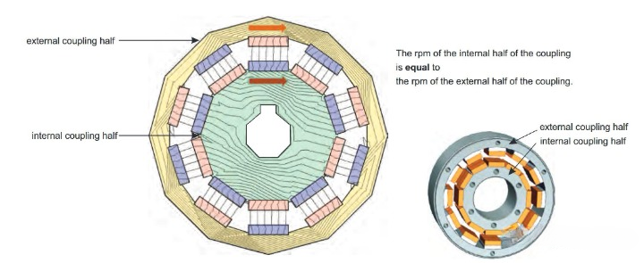
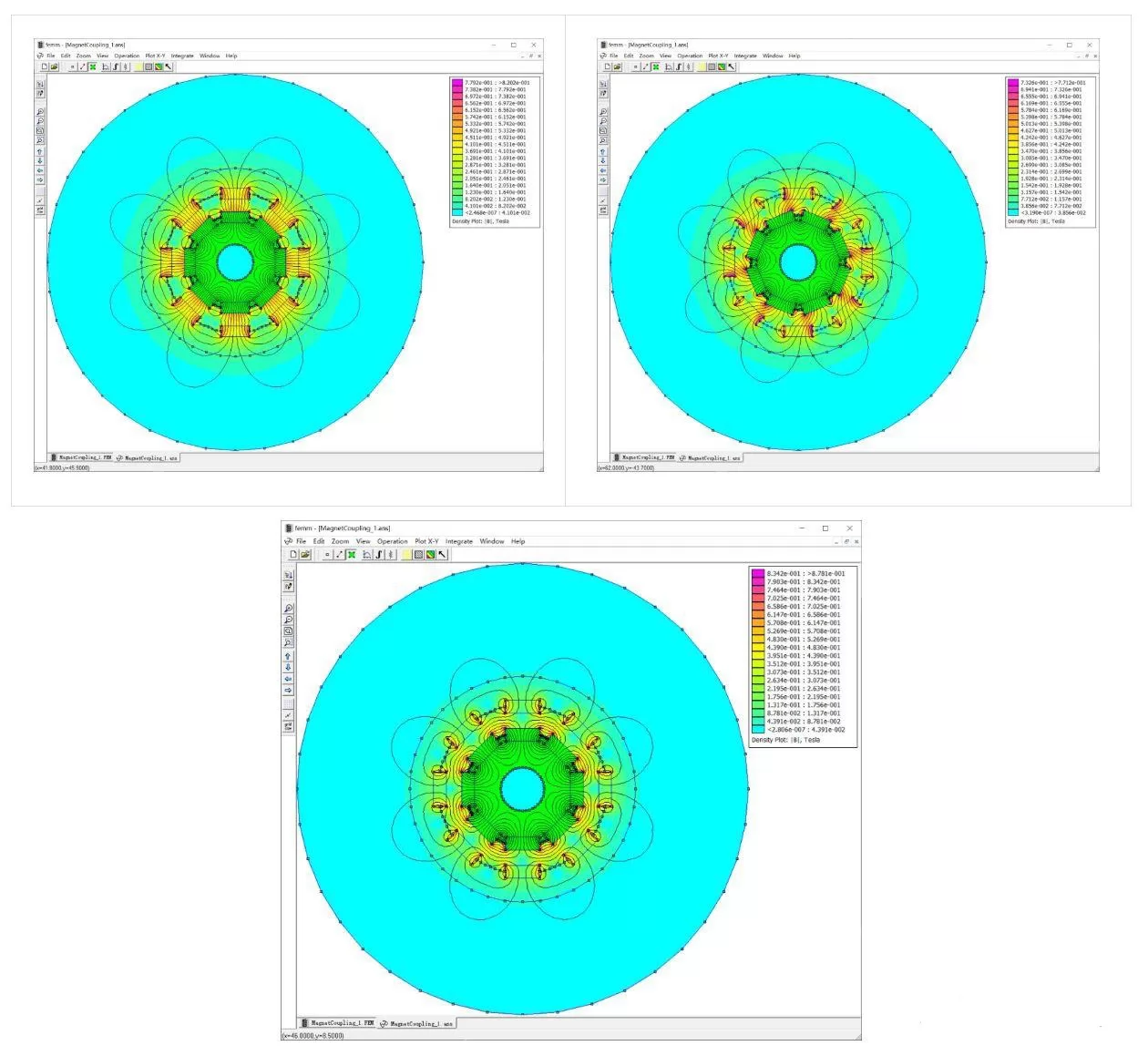
The fundamental operating principle of the magnetic coupling is based on magnetic field coupling between permanent magnets through a non-magnetic barrier material. When two magnetic circuits composed of sintered NdFeB or SmCo permanent magnets — the inner magnetic rotor and the outer magnetic rotor — are separated by a thin wall of non-magnetic metal (316L stainless steel, Hastelloy C, titanium alloy) or non-magnetic non-metal (PTFE, PEEK, ceramic), the magnetic flux lines still cross the barrier wall and form a closed magnetic circuit between the inner and outer rotors.
When an external prime mover (electric motor, steam turbine, internal combustion engine) rotates the outer magnetic rotor, the rotating magnetic field produced by the permanent magnets on the outer rotor crosses the barrier wall and exerts a tangential magnetic force on the permanent magnets of the inner rotor. This tangential magnetic force acts at the effective radius of the inner rotor and produces a torque that drives the inner rotor to follow the outer rotor in synchronous rotation.
The critical engineering characteristic is that there is no mechanical contact whatsoever between the inner and outer rotors — there is no bearing supporting the inner rotor relative to the outer rotor, and there is no seal or packing separating the process media. The only connection between the inner and outer rotors is the magnetic field itself. This non-contact torque transmission characteristic delivers a series of engineering advantages that are impossible to achieve with conventional mechanical couplings, including absolute zero leakage, maintenance-free operation, built-in overload protection, vibration isolation, misalignment tolerance, and explosion-proof safety.
3. Core Engineering Equations — Quantitative Calculation of Torque, Magnetic Force, and Power Loss
3.1 Maxwell Shear Stress
The transmissible shear stress per unit air-gap area in a magnetic coupling is determined by the air-gap magnetic flux density:
τ = B_g² / (2μ₀)
where τ is the shear stress (Pa), B_g is the air-gap magnetic flux density (T), and μ₀ is the permeability of free space (μ₀ = 4π × 10⁻⁷ H/m). When B_g = 0.5 T, τ ≈ 99.5 kPa; when B_g = 0.8 T, τ ≈ 254.6 kPa. This equation is the foundation of magnetic coupling selection — the torque density is proportional to the square of the air-gap magnetic flux density.
3.2 Total Transmissible Torque (Cylindrical Radial Configuration)
For a radial-configuration cylindrical magnetic coupling (outer rotor enclosing the inner rotor), the total transmissible torque is:
T = τ × 2π × r_m² × L
where r_m is the mean air-gap radius (m) and L is the effective axial length (m). Substituting the equation for τ:
T = (B_g² × π × r_m² × L) / μ₀
This is the core equation for engineering selection and determines the maximum transmissible torque of a magnetic coupling at a given envelope size. For example, a standard magnetic coupling with r_m = 50 mm, L = 100 mm, and B_g = 0.7 T can transmit approximately 307 N·m of torque.
3.3 Axial Magnetic Attraction Force
The axial magnetic attraction force between the inner and outer rotors is determined by the projection of the Maxwell stress tensor on the axial direction:
F_z = (B_g² × π × r_m × L) / μ₀
This axial attraction force is typically very large (can reach several thousand newtons) and must be balanced by a thrust bearing. It is one of the key structural design loads for magnetic couplings. The axial force is proportional to the first power of r_m, which differs from the torque relationship.
3.4 Synchronous Torque and Load Angle
For a synchronous magnetic coupling (zero slip), the relationship between the load angle θ and the transmitted torque T is:
T = T_max × sin(n_p × θ)
where T_max is the maximum transmissible torque and n_p is the number of pole pairs. When θ approaches π/(2n_p), the coupling reaches T_max; further increase in load results in step-out (decoupling). This means that the magnetic coupling has a built-in overload protection characteristic — when the load exceeds T_max, the inner and outer rotors slip relative to each other, avoiding mechanical damage, equivalent to a built-in torque limiter.
3.5 Containment Can Eddy Current Loss
The containment can produces eddy current losses in the alternating magnetic field, which is the primary heat source in a magnetic coupling:
P_e = k_e × (π × f × B_g)² × t² × V / ρ
where f is the magnetic field alternating frequency (related to rotational speed and pole count), t is the containment can wall thickness, V is the can volume, ρ is the can material electrical resistivity, and k_e is a constant factor. The eddy current loss is proportional to the square of the wall thickness, so thin-wall designs (typically 0.5-1.5 mm) and high-resistivity materials (such as 316L stainless steel, Hastelloy C) are commonly used in engineering practice to minimize loss.
3.6 Torque Density
The torque density of a magnetic coupling is defined as the transmissible torque per unit effective volume:
σ_T = T / V_total
where V_total is the total volume within the outer rotor outside diameter. A well-designed magnetic coupling achieves σ_T of 50-150 kN·m/m³, which is substantially higher than the torque density achievable with conventional gear couplings or diaphragm couplings.
4. Overall Construction — Five Core Components
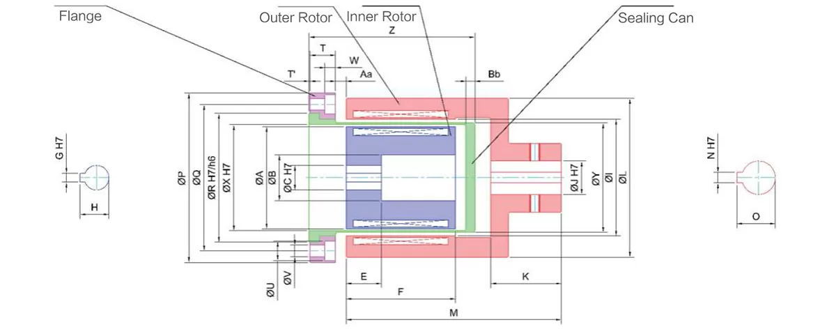
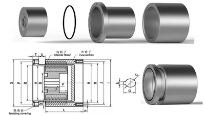
A complete magnetic coupling assembly is composed of the following five core components:
4.1 Outer Magnetic Rotor (Drive Cup)
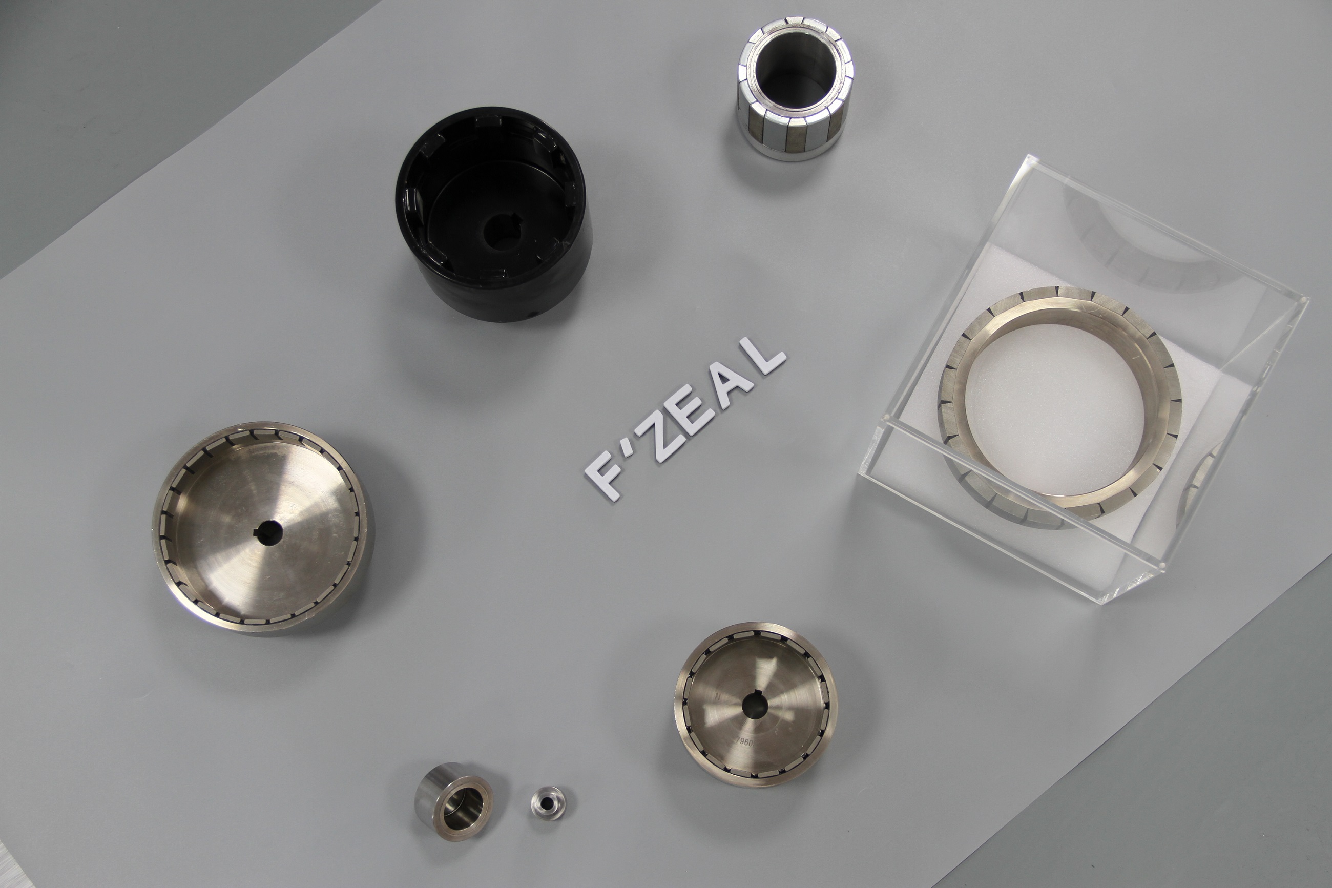
The outer magnetic rotor is the driving-side component of the magnetic coupling. It is typically constructed of a low-carbon steel (1010, 1020) cup body with sintered NdFeB or SmCo arc-shaped permanent magnet segments bonded to the inside surface of the cup. The accompanying Figure 1 in this guide shows a typical outer magnetic rotor — the black epoxy coating covers the magnet segments on the inside surface, providing corrosion protection. The outer magnetic rotor is mounted on the input shaft (motor shaft, turbine shaft) by means of a keyway connection.
4.2 Inner Magnetic Rotor (Driven Hub)
The inner magnetic rotor is the driven-side component of the magnetic coupling. It is typically constructed of a low-carbon steel (1010, 1020) hub with sintered NdFeB or SmCo arc-shaped permanent magnet segments bonded to the outside surface of the hub. The accompanying Figure 2 in this guide shows a typical inner magnetic rotor — the arc-shaped magnet segments on the bare metal outside surface are clearly visible, and the "N" marking indicates the orientation of the North magnetic pole. The inner magnetic rotor is mounted on the output shaft (pump shaft, mixer shaft, agitator shaft) by means of a keyway connection.
4.3 Containment Can (Baffle)
The containment can is the core sealing component of the magnetic coupling, mounted between the outer magnetic rotor and the inner magnetic rotor, completely sealing the process media on the inner rotor side. The containment can material must be non-magnetic, high-strength, and corrosion-resistant, either metal or non-metal. Common material selections include:
• 316L stainless steel: the most common, resistant to general corrosion, high electrical resistivity (low eddy current loss)
• Hastelloy C-276 / C-22: resistant to strong acids, strong alkalis, and chloride ion corrosion
• Titanium alloy Ti Gr2: resistant to seawater and chlorides, lightweight
• Duplex stainless steel 2205: resistant to chloride stress corrosion cracking
• PEEK / PTFE: non-metallic, strong corrosion resistance but low strength
• Alumina / zirconia ceramic: super corrosion-resistant, ultra-low eddy current loss
The containment can wall thickness is typically 0.5-1.5 mm. Thinner walls provide better magnetic performance but lower mechanical strength, requiring a balance between magnetic performance and mechanical strength.
4.4 Bearing System
The magnetic coupling requires two types of bearing support:
• Radial bearings: bear the radial loads (typically transmitted by the pump shaft) and ensure concentric alignment of the inner and outer rotors
• Thrust bearings (axial bearings): bear the axial magnetic attraction force and process pressure, ensuring that the containment can is not compressed axially
Bearing selection directly determines the service life and reliability of the magnetic coupling. Common bearing types include deep groove ball bearings, cylindrical roller bearings, angular contact ball bearings, and journal bearings.
4.5 Housing (Containment Shell)
The housing encloses the entire magnetic coupling assembly, providing mechanical protection, mounting interfaces, and flange connections. The housing is typically manufactured from aluminum alloy, 316L stainless steel, or carbon steel, and provides IP65 or IP67 ingress protection when required.
5. Axial vs Radial Magnetic Coupling Configurations
5.1 Axial / Disc Magnetic Coupling
In an axial or disc magnetic coupling, the inner and outer magnetic rotors are both disc-shaped (pancake configuration) and face each other axially. The permanent magnets are magnetized in the axial direction (axial magnetization), and the magnetic field crosses the containment disc axially.
Advantages:
• Compact in the axial direction, suitable for applications with limited axial space
• Suitable for large diameters (wind power, marine propulsion)
• Very high torque density (higher torque than radial coupling at the same envelope)
Disadvantages:
• Very large axial magnetic attraction force (no self-balancing), requires heavy-duty thrust bearings
• The containment disc is thin and easily deformed under differential pressure
• Pole pair count is limited by the diameter
Typical applications: large mixers, marine propulsion, vertically mounted pumps, centrifuges, wind turbine generators.
5.2 Radial / Cylindrical Magnetic Coupling
In a radial or cylindrical magnetic coupling, the inner and outer magnetic rotors are both cylindrical cup-shaped, arranged concentrically inside one another. The permanent magnets are magnetized in the radial direction (radial magnetization), and the magnetic field crosses the containment can wall radially. The accompanying Figures 1 and 2 in this guide show the inner and outer magnetic rotors of a typical radial magnetic coupling.
Advantages:
• Symmetric structure, axial magnetic attraction force is self-balanced (small thrust bearing load)
• The cylindrical containment can has strong pressure-bearing capability
• Suitable for long axial lengths (high torque)
• Flexible pole pair count selection
• Mature manufacturing process, controllable cost
Disadvantages:
• Larger in the diameter direction
• Lower torque density than axial coupling (at the same envelope size)
Typical applications: chemical pumps, magnetic drive pumps, pharmaceutical pumps, food pumps, nuclear primary loop pumps, submersible mixers, sealed reactor agitators.
5.3 Configuration Selection Decision
For engineering selection, the radial magnetic coupling is suitable for the vast majority of industrial pump and mixing applications and is the market mainstream (approximately 80% market share); the axial magnetic coupling is suitable for special applications requiring large diameter, low rotational speed, and ultra-high torque, such as wind power and marine propulsion. The core selection considerations are axial space limitations, torque requirements, differential pressure conditions, thrust bearing capability, and installation and maintenance convenience.
6. Why Use Magnetic Couplings — Six Core Advantages
6.1 Absolute Zero Leakage
The magnetic coupling achieves complete isolation of the process media from the external environment through the containment can, with zero leakage rate. For toxic and hazardous media (chlorine, benzene, cyanide, acid and alkali solutions), valuable media (catalysts, pharmaceutical liquids, food-grade fluids), and high-purity media (semiconductor ultrapure water, nuclear-grade sodium), zero leakage is a prerequisite for process feasibility.
6.2 Maintenance-Free Operation
The magnetic coupling has no mechanical contact, no seal, no packing, no lubrication requirement, no flushing requirement, MTBF (Mean Time Between Failures) typically ≥ 30,000 hours, design service life 10-20 years. Compared with mechanical seal pumps, the annual maintenance cost is reduced by 70%-90%.
6.3 Built-in Overload Protection
When the load torque exceeds the maximum transmissible torque T_max of the magnetic coupling, the inner and outer rotors slip relative to each other (slip), and the input shaft continues to rotate while the output shaft stops. This magnetic slip characteristic avoids mechanical damage (broken shaft, burned motor), equivalent to a built-in torque limiter.
6.4 Vibration Isolation
The magnetic field transmission of the magnetic coupling is flexible — it absorbs micro-vibrations in the radial, axial, and angular directions. This is critical for precision processes such as semiconductor wafer processing, laser systems, and precision chemical processing.
6.5 Misalignment Tolerance
The magnetic coupling tolerates a certain degree of radial, axial, and angular misalignment (typically ±1-3 mm radial, ±2-5 mm axial, ±0.5-2° angular). This reduces the installation precision requirements and simplifies on-site commissioning.
6.6 Explosion-Proof Safety
The magnetic coupling has no friction, no sparks, no high-temperature surface, and meets ATEX and IECEx explosion-proof certification requirements, suitable for flammable and explosive media (gasoline, alcohol, organic solvents).
7. Key Application Industries — 9 Industries and 24 Sub-Scenarios
7.1 Chemical Processing
• Strong acid and alkali transfer pumps (sulfuric acid, hydrochloric acid, sodium hydroxide)
• Toxic media transfer pumps (chlorine, benzene, cyanide)
• Flammable and explosive media transfer pumps (gasoline, alcohol, acetone)
• Catalyst circulation pumps
• Reactor agitators
7.2 Pharmaceutical
• Sterile API transfer pumps (GMP compliant)
• Water for injection (WFI) circulation pumps
• Bioreactor agitators
• Herbal extract transfer pumps
• Lyophilizer vacuum pumps
7.3 Food and Beverage
• Milk, juice, and beer transfer pumps (3A sanitary certified)
• Edible oil refining pumps
• Syrup and chocolate paste transfer pumps
• Beverage mixing agitators
7.4 Oil and Gas
• Offshore platform process pumps (API 685 standard)
• Liquefied natural gas (LNG) cryogenic pumps
• Crude oil transfer pumps
• Tanker ballast pumps
• Drilling mud pumps
7.5 Nuclear Power
• Nuclear island primary loop main pumps (ASME III class certified)
• Spent fuel pool cooling pumps
• Radioactive wastewater transfer pumps
• Reactor cavity flooding pumps
7.6 Semiconductor
• Ultrapure water (UPW) transfer pumps
• Chemical transfer pumps (HF, H₂SO₄, H₂O₂)
• CMP slurry circulation pumps
• Wafer cleaning equipment agitators
7.7 Water Treatment
• Seawater desalination high-pressure pumps
• Submersible sewage pumps
• Water chlorination and dosing pumps
• Industrial wastewater treatment pumps
7.8 Medical
• Extracorporeal circulation pumps (cardiac surgery)
• Hemodialysis fluid circulation pumps
• Medical gas transfer pumps
• Pharmaceutical purified water circulation pumps
7.9 Aerospace
• Aviation hydraulic system power transmission
• Satellite propellant transfer pumps
• Rocket engine oxidizer pumps
• Flight control hydraulic pumps
8. Engineering Selection Considerations and Certification Standards
When selecting a magnetic coupling, the engineer must comprehensively consider the following key parameters:
Torque requirement: T_required = T_operating × safety factor (typically 1.5-2.0), should not exceed 0.8 × T_max.
Speed range: At high rotational speeds, eddy current losses increase, requiring high-resistivity containment can materials (such as Hastelloy). The maximum rotational speed for a synchronous magnetic coupling is typically ≤ 6,000 RPM.
Containment can pressure rating: Selected based on the maximum process side working pressure (including water hammer) for the containment can wall thickness and material. Generally up to 50 bar is achievable, with high-pressure designs achieving 100 bar or more.
Temperature range: NdFeB magnet maximum continuous operating temperature 80-200°C (depending on grade N35-N52, SH/UH/EH/AH), SmCo can reach 350°C. The containment can material must match the process temperature.
Media compatibility: The containment can material and the magnet surface coating (Ni, NiCuNi, epoxy, PTFE) must be compatible with the process media, avoiding corrosion, swelling, or catalytic reactions.
Certification requirements: API 685 (petroleum), 3A sanitary standards (food), GMP (pharmaceutical), ATEX/IECEx (explosion-proof), ASME III (nuclear), FDA (food contact).
9. SEO Keyword Index
Primary keywords: magnetic coupling, permanent magnet coupling, non-contact magnetic drive, magnetic drive coupling, sealless magnetic coupling, hermetic magnetic coupling, magnetic drive pump, magnetic coupling manufacturer, magnetic coupling supplier, through-wall torque transmission.
Secondary keywords: NdFeB magnetic coupling, SmCo magnetic coupling, Halbach array magnetic coupling, axial magnetic coupling, radial magnetic coupling, disc type magnetic coupling, cylindrical magnetic coupling, magnetic torque transmission, magnetic shaft coupling, magnetic clutch alternative.
Long-tail keywords: API 685 magnetic coupling, ATEX magnetic coupling, 3A sanitary magnetic coupling, chemical pump magnetic coupling, pharmaceutical pump magnetic coupling, food grade magnetic coupling, nuclear primary pump magnetic coupling, magnetic coupling operating principle, magnetic coupling structure, magnetic coupling selection guide, magnetic coupling manufacturer China, custom magnetic coupling, eddy current loss containment can, synchronous magnetic coupling, magnetic coupling for hazardous chemicals.
Application keywords: chemical processing, pharmaceutical, petrochemical, nuclear power, offshore engineering, semiconductor, food and beverage, medical, water treatment, aerospace.
FAIZEAL — Custom Permanent Magnet Magnetic Couplings, Magnetic Drive Pumps, and Non-Contact Torque Transmission Assemblies. Ningbo, China. Established 2017. Sintered NdFeB and SmCo permanent magnet materials. ISO 9001 quality management. API 685 / ATEX / 3A / GMP / ASME III compliance support. Global shipping. Engineering support in English and Chinese.
0
Comments
Leave a Comment
Your email address will not be published. Required fields are marked *
Name can't be empty
Email error!
Message can't be empty
😍
😜
😳
😌
😄
😘
😝
😒
😃
😚
😚
😛
😟
😧
😀
😉
😓
😱
😤
😣
😂
😥
😩
😠
😢
😭
😰
😨
😡
😆
😪
😅
😐
😇
😋
😴
👿
😕
😏
😷
😵
😟
😮
😯
😑
👧
👴
😧
😬
😾
👶
👱
👵
👸
🙀
👺
👦
👩
👨
😽
😿
🙈
💩
💥
💤
😼
😹
🙉
🔥
✨
💦
👎
✌
👆
👈
💪
💹
👍
👊
💴
💶
💷
💸
👉
💵
🙏
🌎
🏧
👏
💳
👇
💑
🙆
🙅
💁
👫
👭
🙎
🙇
👑
👔
Submit Comment
Most Popular
-
 Dec 25, 2024Top 10 Ndfeb Magnet Manufacturers and Suppliers in the World 2025
 -
 Jun 18, 2026What is a Magnet Made of and How Does it Work?
 -
 Sep 27, 2023What is a Magnetic Wheel and How Does it Work
 -
 Sep 28, 2023Top 10 Permanent Magnet Motor Rotor Manufacturers in the World


Laster Blogs
-
 Sep 16, 2026Operation of Non-contact Magnetic Couplings
 -
 Sep 16, 2026High-Temperature Resistant Bonding Solution for Flat Rotor Magnets in Robot Joint Motors
 -
Jun 18, 2026What is a Magnet Made of and How Does it Work?
-
 Jun 05, 2026Magnetic Wheels vs Manual Labor: A New Chapter in Wind Turbine Cleaning and Inspection


Set A Consultation Today
Name can't be empty
Email error!
Send Your Message
*We respect your confidentiality and all
information are protected.