Principles and Applications of Halbach Arrays
FAIZEAL — Halbach Array Operating Principle
Halbach Array Operating Principle and Engineering Applications — Complete Engineering Guide for Permanent Magnet Circuit Optimization
Halbach Array Theory, Design, Manufacturing, and Applications in Electric Motors, Wind Power, Robotics, MRI, Maglev, and Particle Accelerators
Halbach array / Halbach permanent magnet array / one-sided flux array / self-shielding magnet array / cylindrical Halbach / linear Halbach / NdFeB Halbach / SmCo Halbach / Halbach rotor / Halbach motor / Halbach array manufacturer / Halbach array principle / Halbach array design / robot joint motor / wind generator / MRI / maglev / particle accelerator
1. Introduction — Halbach Array: The Revolutionary Breakthrough in Permanent Magnet Circuit Optimization
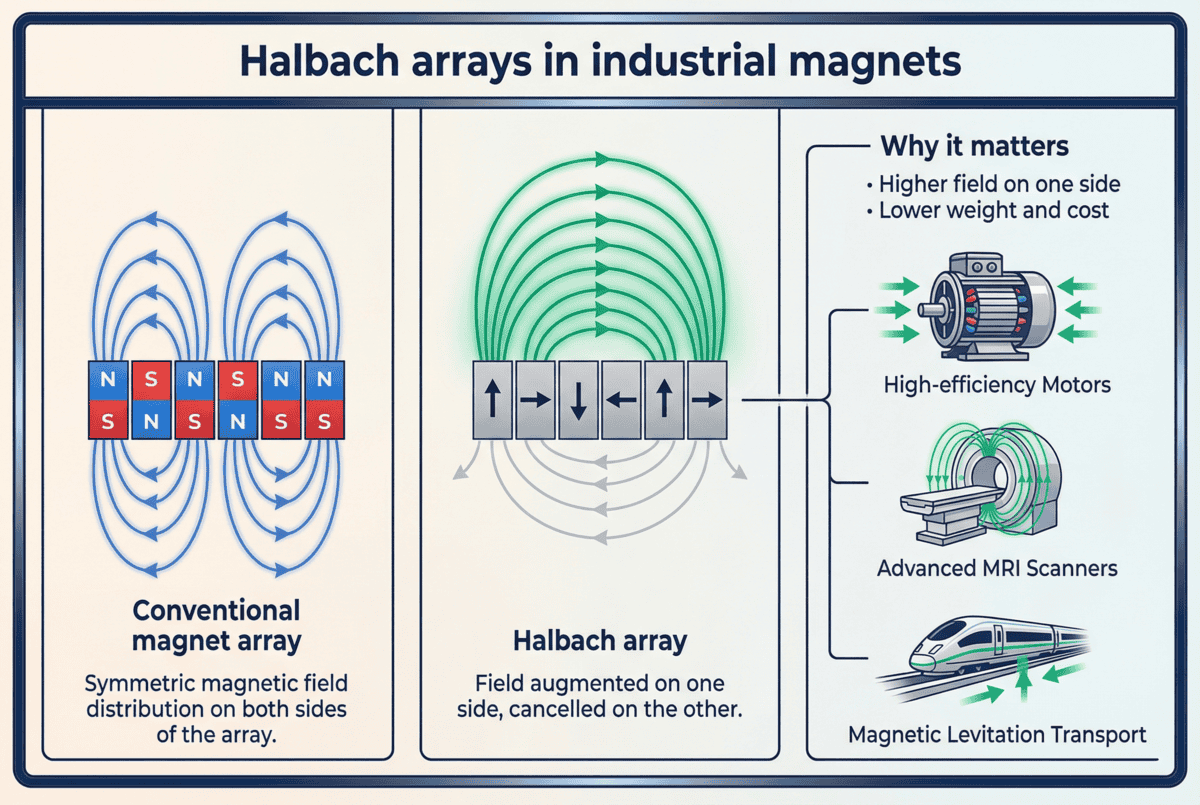
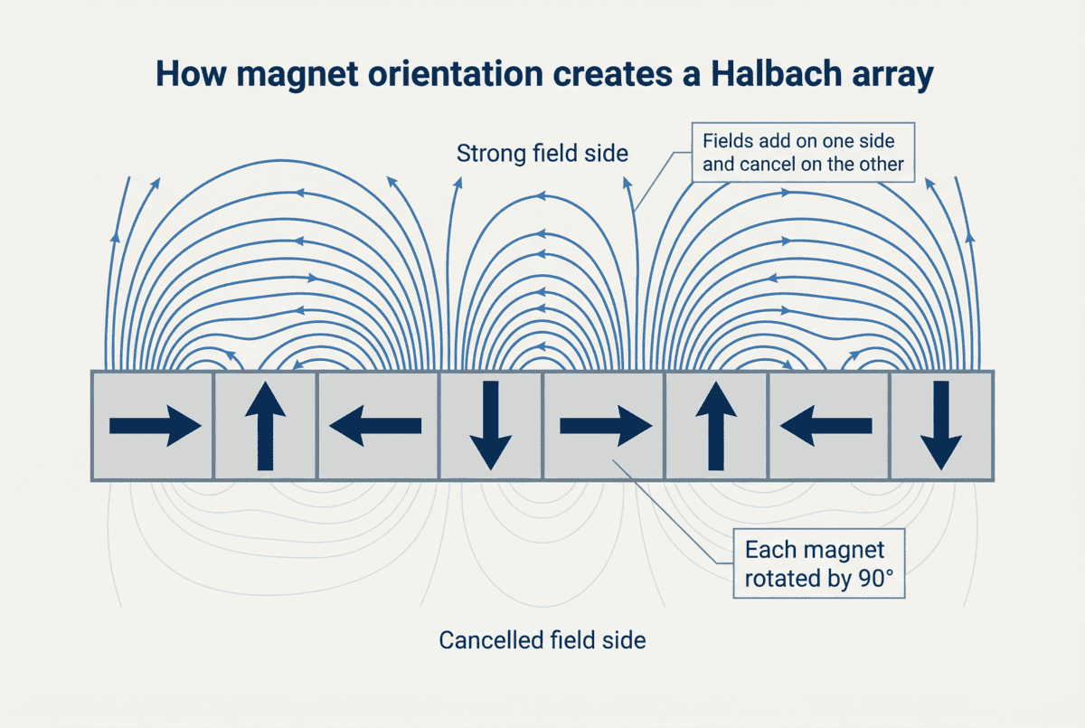
The Halbach array, also known as the Halbach permanent magnet array, one-sided flux array, or self-shielding magnet array, is a special permanent magnet arrangement first proposed by American physicist Klaus Halbach at the Lawrence Berkeley National Laboratory in 1979. The Halbach array precisely controls the magnetization direction of each permanent magnet element so that the magnetic fields superimpose constructively on one side of the array while canceling on the opposite side, achieving the revolutionary effect of one-sided flux concentration.
Since 1979, Halbach arrays have been widely applied in numerous high-technology fields, including particle accelerators, free-electron lasers, medical magnetic resonance imaging (MRI), maglev trains, wind generators, permanent magnet synchronous motors (PMSM), brushless DC motors (BLDC), robot joint motors, magnetic bearings, and magnetic refrigeration. The core value of the Halbach array is that it increases the air-gap magnetic flux density by 30-50% without increasing the permanent magnet material volume, while significantly reducing the rotor mass, increasing the motor torque density, and reducing the cogging torque.
This engineering guide systematically describes the operating principle of the Halbach array, the core engineering equations, the array types, the key advantages, the material selection, the manufacturing process, the main application industries, the design considerations, and the selection guidelines. This guide is intended for Halbach array design engineers, permanent magnet motor engineers, maglev system engineers, robot joint motor engineers, MRI equipment engineers, and technical procurement specialists.
2. Operating Principle — Magnetic Field Vector Superposition and One-Sided Flux Concentration
The core operating principle of the Halbach array is based on the precise spatial arrangement of permanent magnet magnetization vectors. In a conventional radial magnetization permanent magnet rotor, all magnet segments are magnetized pointing toward the rotor center (radially outward or inward), and the magnetic field is symmetrically distributed on both the air-gap side and the rotor back-iron side.
In a Halbach array, the magnetization direction of each magnet segment varies according to a precise mathematical law: the main pole segments are radially magnetized, the auxiliary pole segments are tangentially or obliquely magnetized, and the magnetization vectors of all magnet segments are arranged at specific angles. When these magnetization vectors are superimposed in space, the magnetic field components on the air-gap side superimpose constructively, while the magnetic field components on the back-iron side mutually cancel and decay. This self-shielding characteristic enables the Halbach array to produce air-gap magnetic flux densities far higher than those of conventional radial magnetization arrangements.
For an ideal cylindrical Halbach array with continuously varying magnetization (infinite segmentation), the magnetization vector continuously rotates in space, mathematically described as:
M(θ) = M_r × [cos(kθ) × r̂ + sin(kθ) × θ̂]
where M_r is the permanent magnet remanent magnetization, k is the spatial frequency (k = n_p × 2π/L, n_p is the pole pair count), and r̂ and θ̂ are the radial and tangential unit vectors.
3. Core Engineering Equations — Quantitative Calculation of Field Gain, Torque, and Magnetic Force
3.1 Field Gain Factor
The core equation of the Halbach array is the field gain factor G, which quantitatively describes the air-gap magnetic flux density improvement of the Halbach array relative to conventional radial magnetization:
G(n) = 1 + cos(2π/n)
where n is the number of magnet segments per pole pair. This equation reveals the key design rule of Halbach arrays:
• When n = 2 (only 2 segments per pole pair, no Halbach effect), G = 0, equivalent to conventional radial magnetization
• When n = 3 (3 segments per pole pair), G = 1.5, air-gap flux density improved by 50%
• When n = 4 (4 segments per pole pair), G ≈ 1.707, improved by 70.7%
• When n = 5, G ≈ 1.809
• When n = 6, G ≈ 1.866
• When n = 8, G ≈ 1.924
• When n → ∞ (continuous variation), G → 2, ultimate gain of 100%
In engineering practice, n = 3-6 is the most common choice, balancing magnetic performance improvement with manufacturing complexity.
3.2 Air-Gap Magnetic Flux Density
The magnetic flux density produced by the Halbach array in the air gap is:
B_g = B_r × k_fill × G(n) × (geometry factor)
where B_r is the permanent magnet remanence (typical NdFeB N52: B_r = 1.42-1.48 T; N42SH: B_r = 1.28-1.32 T), k_fill is the magnet filling factor (typical 0.85-0.95), G(n) is the field gain factor, and geometry factor is the correction factor related to the specific geometry (typical 0.7-0.9).
For a typical NdFeB N52 Halbach array with n=4, k_fill=0.9, and geometry=0.85, the air-gap flux density can reach:
B_g ≈ 1.45 × 0.9 × 1.707 × 0.85 ≈ 1.89 T
This magnetic flux density is close to the theoretical limit of NdFeB material, far higher than the 1.0-1.2 T achievable with conventional radial magnetization.
3.3 Total Torque (Cylindrical Halbach Rotor)
The total torque of a cylindrical Halbach rotor is:
T = (B_g² × π × r_m² × L) / μ₀
Since B_g is increased by 30-50%, the torque T is correspondingly increased by 70-125% (proportional to the square of B_g). This is the fundamental reason why Halbach array motors can substantially increase the motor torque density.
3.4 Cogging Torque Reduction
The magnetic field distribution of the Halbach array is close to a sinusoidal wave, which reduces the cogging torque by 60-80% compared to conventional radial magnetization. The approximate equation for cogging torque is:
T_cog ≈ (π × L × B_g² × D_s × N_s × sin(N_s × θ_s)) / (4 × μ₀ × N_p × δ)
where D_s is the stator diameter, N_s is the number of stator slots, N_p is the number of poles, θ_s is the skew angle, and δ is the air-gap length. Due to the high sinusoidal quality of the Halbach array magnetic field, the cogging torque amplitude is substantially reduced.
3.5 Torque Density Enhancement
The torque density of a Halbach array motor is defined as the torque per unit effective volume:
σ_T = T / V_total
Since the air-gap flux density is increased by 30-50%, the torque density is correspondingly increased by 70-125%. The torque density of Halbach array motors can reach 80-200 kN·m/m³, far higher than the 50-100 kN·m/m³ achievable with conventional radial magnetization motors.
3.6 Radial Magnetic Force
The radial magnetic attraction force produced by the Halbach array is:
F_r = (B_g² × π × r_m × L) / (2μ₀)
The radial force is half of the axial force, but it still needs to be supported by bearings, and is a key design parameter for Halbach bearings.
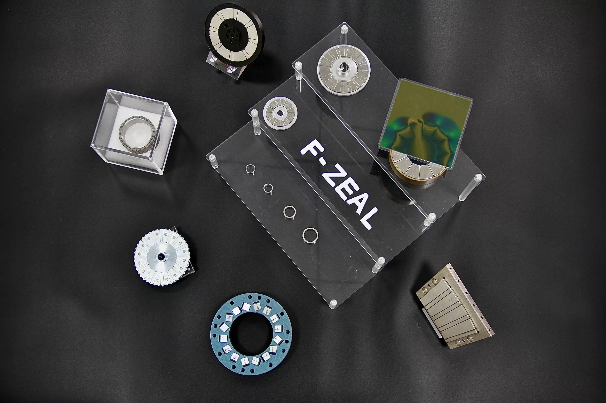
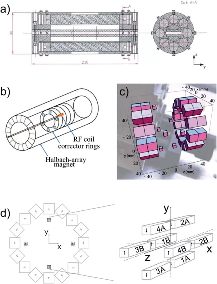
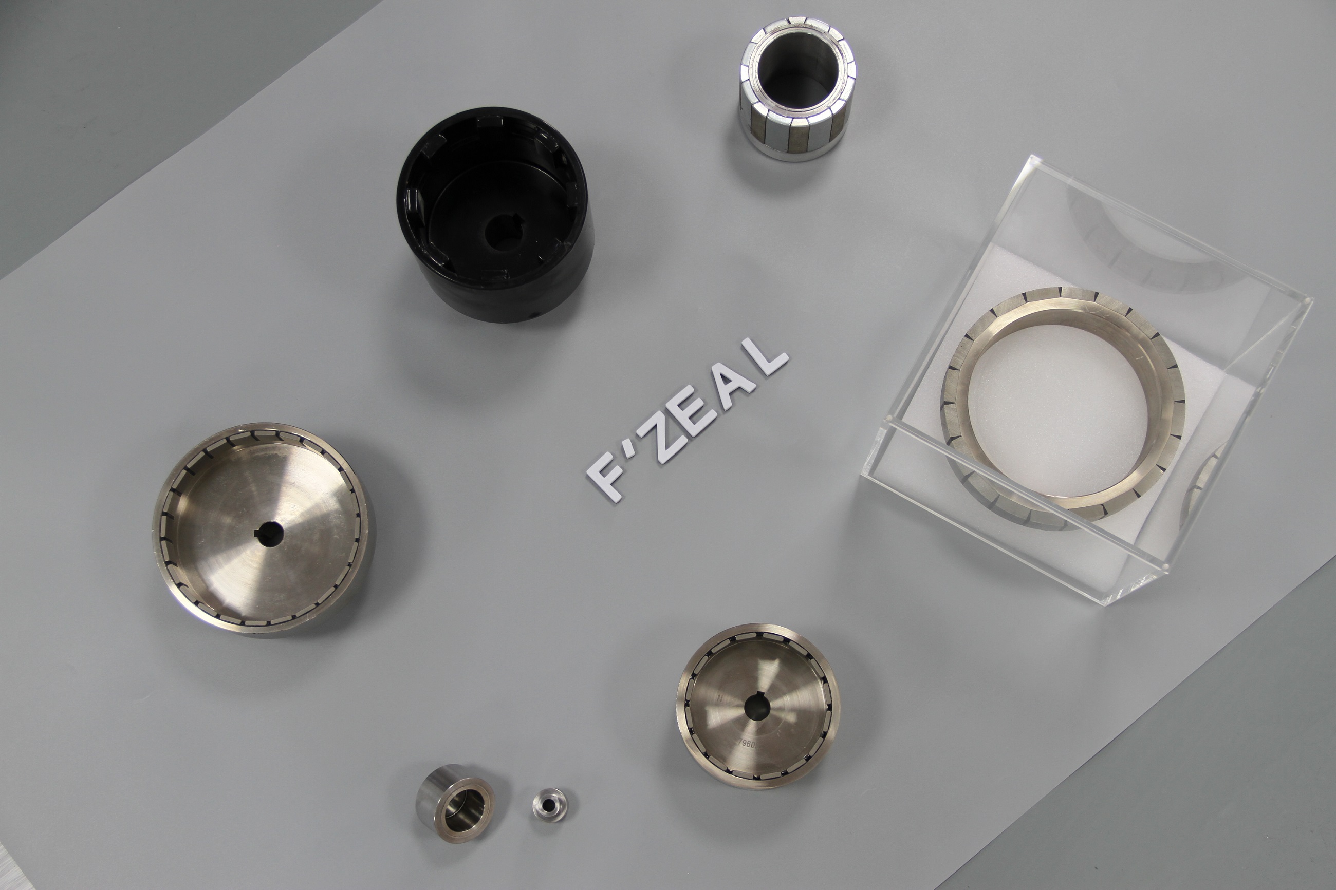
Some Halbach array magnetic assemblies previously manufactured by FAIZEAL.
4. Halbach Array Types — Four Main Configurations
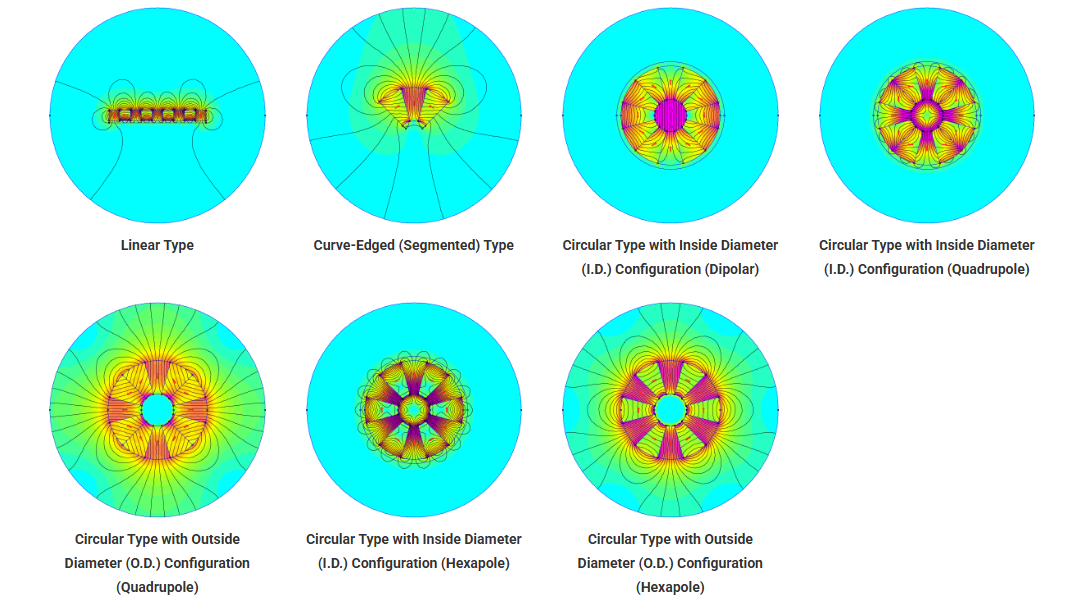
The Halbach array can be classified into four main configurations based on its geometric form:
4.1 Linear Halbach Array
The linear Halbach array is the most basic configuration. All magnet segments are arranged along a straight line, and the magnetization vector rotates in the plane. The linear Halbach array is primarily used for:
• Linear motors
• Maglev trains
• Free-electron lasers
• Particle accelerators
Advantages: simple structure, easy to manufacture; magnetic field highly concentrated in the vertical direction.
4.2 Cylindrical Halbach Array
The cylindrical Halbach array is the most common engineering configuration. The magnet segments are arranged on the cylindrical surface, and the magnetization vector rotates on the cylindrical surface. FAIZEAL's standard arc-segment-assembled Halbach rotor (sintered NdFeB arc segments + steel back-iron + steel shaft sleeve) is a typical cylindrical Halbach array, and is the core technology used in our robot joint motors and magnetic couplings.
The cylindrical Halbach array is primarily used for:
• Permanent magnet synchronous motors (PMSM)
• Brushless DC motors (BLDC)
• Robot joint motors
• Wind generators
• Magnetic bearings
Advantages: compact structure, high torque density, good mechanical strength.
4.3 Spherical Halbach Array
The spherical Halbach array is a three-dimensional configuration. The magnet segments are arranged on the spherical surface, and the magnetization vector rotates on the spherical surface. The spherical Halbach array is primarily used for:
• Magnetic resonance imaging (MRI) main magnets
• Spherical motors
• Special magnetic levitation devices
Advantages: three-dimensional magnetic field symmetry, no directional preference; complex manufacturing, high cost.
4.4 Bilateral / Double Halbach Array
The bilateral Halbach array arranges Halbach arrays on both the inner and outer sides of a cylinder to produce a symmetric bilateral magnetic field. The bilateral Halbach array is primarily used for:
• Inner-rotor + outer-rotor motors
• Magnetic couplings
• High torque density special motors
4.5 Skewed and Segmented Halbach
In engineering practice, the Halbach array often uses segmented skew (skewed Halbach) to further reduce cogging torque and vibration noise. The skew angle is typically half a stator slot pitch, which can reduce the cogging torque by more than 90%.
5. Why Use Halbach Arrays — Seven Core Advantages
5.1 Air-Gap Flux Density Improved by 30-50%
This is the most core advantage of the Halbach array. Through precise magnetization vector arrangement, the Halbach array can improve the air-gap magnetic flux density by 30-50% without increasing the permanent magnet material volume. For N52 NdFeB + 4-segment Halbach array, the air-gap flux density can reach 1.7-1.9 T, close to the physical limit of NdFeB material.
5.2 Self-Shielding Effect
The Halbach array enhances the magnetic field on the air-gap side while almost completely canceling the magnetic field on the back-iron side. This self-shielding effect allows the Halbach rotor to substantially reduce or even completely eliminate the back-iron, thereby:
• Reducing rotor mass by 20-40%
• Decreasing rotor moment of inertia
• Improving motor dynamic response speed
5.3 Higher Torque Density
Since the air-gap flux density is increased by 30-50% and the torque is proportional to the square of B, the torque density of Halbach array motors is increased by 70-125% compared to conventional radial magnetization motors. This is critical for high torque density applications such as robot joint motors, wind generators, and electric vehicle drive motors.
5.4 Near-Sinusoidal Magnetic Field Waveform
The magnetic field distribution of the Halbach array is close to a sinusoidal wave in space, which delivers lower cogging torque, lower torque ripple, and lower vibration noise. This is particularly important for precision robots, servo motors, and medical equipment.
5.5 Simplified Manufacturing and Assembly
Since the Halbach array back-iron can be reduced or even eliminated, the rotor structure is substantially simplified. This reduces material cost, processing cost, and assembly cost. At the same time, because the magnetic field is cleaner, the magnetic saturation pressure on the stator core is reduced.
5.6 Improved Motor Efficiency
The high air-gap flux density and low cogging torque of the Halbach array improve the motor efficiency by 2-5%. For electric vehicles and wind generators, every 1% efficiency improvement represents substantial energy savings.
5.7 Strong Compatibility
The Halbach array is compatible with existing motor topologies (PMSM, BLDC, axial flux, radial flux), serving as an upgraded version of existing motors rather than a replacement. Existing motor designs can obtain performance improvement simply by replacing the rotor magnetic circuit with a Halbach array, without modifying the stator, control system, or cooling system.
6. Material Selection and Manufacturing Process
6.1 Sintered Neodymium Iron Boron (Sintered NdFeB)
The most common Halbach array material, with high remanence (typical N52: B_r = 1.42-1.48 T) and large magnetic energy product (BH_max = 380-420 kJ/m³). Common grade selections include:
• N35-N52: room temperature applications (below 80°C)
• N42SH / N40UH: elevated temperature applications (below 180°C)
• N38EH / N35AH: ultra-high temperature applications (below 200°C)
6.2 Samarium Cobalt (SmCo)
Suitable for ultra-high temperature (above 200°C) or ultra-low temperature (liquid nitrogen, liquid helium) applications. Slightly lower remanence than NdFeB, but excellent temperature stability. Common grades include:
• SmCo₅: good temperature stability, moderate cost
• Sm₂Co₁₇: large magnetic energy product, best temperature stability
6.3 Bonded Neodymium Iron Boron (Bonded NdFeB)
Suitable for complex shapes (such as ring-shaped, special-shaped segments), but with lower magnetic performance than sintered NdFeB (remanence approximately 0.6-0.9 T). Commonly used for small batches or special-shaped Halbach arrays.
6.4 Aluminum Nickel Cobalt (AlNiCo)
Excellent temperature stability, but low remanence (typical 0.6-1.2 T) and small magnetic energy product (typical 10-85 kJ/m³), used only for special temperature-sensitive applications.
6.5 Manufacturing Process
The Halbach array manufacturing process mainly includes the following steps:
• Sintered magnet segment cutting: the sintered NdFeB block material is cut into precise arc-shaped segments by wire electrical discharge machining (Wire EDM) or diamond grinding wheel cutting. Arc width tolerance ±0.03 to ±0.05 mm, thickness tolerance ±0.02 mm, angle tolerance ±0.5°
• Surface grinding: precision ground to ensure uniform assembly air gap, surface roughness Ra ≤ 0.8 μm
• Surface treatment: Ni-Cu-Ni three-layer plating, epoxy coating, PTFE coating, or zinc plating selected based on medium environment
• Magnetization: assembly magnetization (assemble first then magnetize, fixture completes magnetization in one operation) or segment pre-magnetization (each segment magnetized individually to precise direction then assembled)
• Assembly and bonding: bonded to steel back-iron using epoxy structural adhesive, cured at 80-150°C × 2-6 hours
• Dynamic balancing: high-speed rotating Halbach rotors require G1.0-G2.5 grade dynamic balance correction (ISO 1940)
• Magnetic flux distribution testing: 100% inspection for each unit including surface magnetic flux density scanning, polarity direction check, and magnetic flux distribution sinusoidal quality FFT evaluation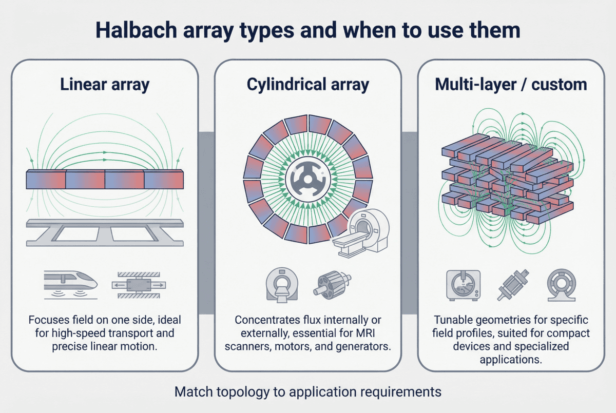
7. Key Application Industries — 10 Industries and 30 Sub-Scenarios
7.1 Electric Vehicles and Hybrid Electric Vehicles (EV & HEV)
• Permanent magnet synchronous traction motors
• Electric air conditioning compressors
• Electric power steering motors (EPS)
• Electric water pumps and oil pumps
7.2 Industrial Automation and Robotics
• Robot joint servo motors
• Collaborative robot joint motors (cobot actuators)
• AGV drive motors
• CNC machine tool spindle motors
7.3 Wind Power Generation
• Direct-drive permanent magnet wind generators (PMSG)
• Semi-direct-drive wind generators
• Offshore wind floating platform generators
7.4 Medical Equipment
• MRI main magnets
• MRI gradient coils
• Proton therapy equipment
• Medical maglev artificial heart pumps
7.5 Aerospace
• Satellite attitude control reaction wheels
• Rocket turbopumps
• Aircraft hydraulic system motors
• UAV motors
7.6 Magnetic Levitation Transportation (Maglev)
• Maglev train propulsion motors
• Magnetic levitation bearings
• Vacuum tube transportation (hyperloop)
7.7 Particle Physics and Scientific Research
• Particle accelerator permanent magnets
• Free-electron lasers
• Neutron source devices
• High-energy physics experimental devices
7.8 Magnetic Bearings and Non-Contact Transmission
• Magnetic levitation flywheel energy storage
• Magnetic bearing compressors
• Magnetic drive pumps
• Magnetic couplings
7.9 Marine Engineering and Naval Applications
• Ship propulsion motors
• Ship degaussing systems
• Underwater vehicle motors
• Offshore platform motors
7.10 Consumer Electronics and Home Appliances
• Hard disk spindle motors
• Air conditioning compressors
• Washing machine variable frequency motors
• High-speed fan motors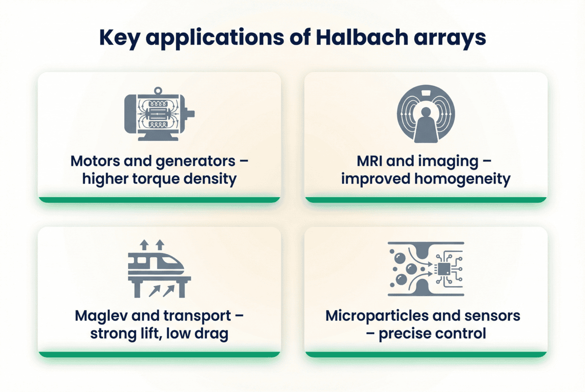
8. Design Considerations and Selection Guidelines
8.1 Number of Segments per Pole Pair
n = 3-4 is the most cost-effective choice. n = 3 provides 50% gain, n = 4 provides 70.7% gain with better manufacturing tolerance. When n > 6, the gain improvement has diminishing marginal returns but manufacturing difficulty increases substantially.
8.2 Pole Count Selection
• Robot joint motors: 8-20 poles (low speed, high torque)
• Servo motors: 4-8 poles (medium-high speed)
• Wind generators: 40-100 poles (ultra-low speed, high torque)
• Electric vehicle motors: 6-12 poles (medium-high speed)
8.3 Back-Iron Design
Due to the self-shielding effect of the Halbach array, the back-iron can be reduced or even eliminated. The no-back-iron design can reduce weight by 20-40%, but requires alternative mechanical fixation (such as carbon fiber wrapping, aluminum sleeve). The Halbach array with back-iron has better structural strength and is convenient for high-speed rotation.
8.4 Temperature and Cooling
The high magnetic flux density of the Halbach array means high power density and high heat generation. The design must comprehensively consider:
• Maximum operating temperature of the permanent magnet (affecting grade selection)
• Rotor cooling (air cooling, water cooling, oil cooling)
• Demagnetization safety margin (typically ≥1.5 times the working point H)
8.5 Cost Trade-Off
The Halbach array costs 30-80% more than conventional radial magnetization, mainly from:
• Multi-segment magnet cutting cost
• Assembly magnetization fixture cost
• Assembly precision requirement
• Inspection cost
But the performance improvement (torque density +70-125%, weight -20-40%) can completely offset the cost premium in high-end applications.
9. SEO Keyword Index
Primary keywords: Halbach array, Halbach permanent magnet array, one-sided flux array, self-shielding magnet array, Halbach motor, Halbach rotor, Halbach array manufacturer, Halbach array principle, Halbach array design, Halbach array applications.
Secondary keywords: cylindrical Halbach array, linear Halbach array, spherical Halbach array, NdFeB Halbach array, SmCo Halbach array, sintered Halbach array, bonded Halbach array, Halbach array field gain, Halbach array torque density, Halbach array robot motor, Halbach array wind generator, Halbach array MRI, Halbach array maglev.
Long-tail keywords: Halbach array flux density improvement, Halbach array cogging torque reduction, Halbach array manufacturing process, Halbach array magnetization fixture, Halbach array back-iron design, Halbach array pole count selection, Halbach array grade selection, custom Halbach array manufacturer China, Halbach array supplier for robot joint, Halbach array for medical MRI, Halbach array for maglev train, Halbach array for particle accelerator, Halbach array with no back-iron, skewed Halbach array.
Application keywords: electric vehicle, industrial automation, robotics, wind power generation, medical equipment, aerospace, maglev transportation, particle physics, magnetic bearings, marine engineering, consumer electronics, BLDC motor, PMSM motor, robot joint motor.
FAIZEAL — Custom Halbach Array Permanent Magnet Assemblies, NdFeB and SmCo Halbach Rotors for High-Performance Motors, Wind Generators, MRI Systems, and Maglev Applications. Ningbo, China. Established 2017. Sintered NdFeB and SmCo permanent magnet materials. ISO 9001 quality management. Global shipping. Engineering support in English and Chinese.
1.Referenced image:https://mainrichmagnets.com/halbach-array-industrial-magnets
2.Referenced image:https://www.researchgate.net/profile/Peter-Bluemler
0
Comments
Leave a Comment
Your email address will not be published. Required fields are marked *
Name can't be empty
Email error!
Message can't be empty
😍
😜
😳
😌
😄
😘
😝
😒
😃
😚
😚
😛
😟
😧
😀
😉
😓
😱
😤
😣
😂
😥
😩
😠
😢
😭
😰
😨
😡
😆
😪
😅
😐
😇
😋
😴
👿
😕
😏
😷
😵
😟
😮
😯
😑
👧
👴
😧
😬
😾
👶
👱
👵
👸
🙀
👺
👦
👩
👨
😽
😿
🙈
💩
💥
💤
😼
😹
🙉
🔥
✨
💦
👎
✌
👆
👈
💪
💹
👍
👊
💴
💶
💷
💸
👉
💵
🙏
🌎
🏧
👏
💳
👇
💑
🙆
🙅
💁
👫
👭
🙎
🙇
👑
👔
Submit Comment
Most Popular
-
 Dec 25, 2024Top 10 Ndfeb Magnet Manufacturers and Suppliers in the World 2025
 -
 Sep 27, 2023What is a Magnetic Wheel and How Does it Work
 -
 Jun 18, 2026What is a Magnet Made of and How Does it Work?
 -
 Sep 16, 2026Operation of Non-contact Magnetic Couplings


Laster Blogs


Set A Consultation Today
Name can't be empty
Email error!
Send Your Message
*We respect your confidentiality and all
information are protected.