
+86-574-87520996
sales@fzmag.com
FAIZEAL
OEM U-Channel Linear Motor for Industrial Direct Drive
Custom Sintered NdFeB Ironless / Iron-Core Forcer — Zero Cogging, High Acceleration, Built to Your Travel & Force-Speed
Semiconductor | Machine Tool | Photonics Alignment | Robotics | ATEX on Request
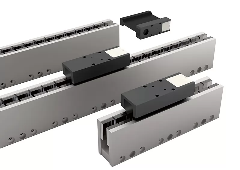

CUSTOM U-CHANNEL LINEAR MOTOR — IRONLESS & IRON-CORE
Direct-Drive, Cogging-Free, Built to Your Travel Length & Force-Speed Envelope
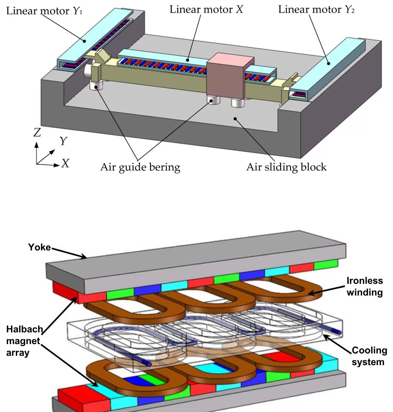

A linear motor is an electric motor that has had its stator and rotor "unrolled" so that, instead of producing a torque (rotation), it produces a linear force along its length. The forcer (the moving part) is suspended in a magnetic field generated by a stationary magnet track, and is propelled by electromagnetic force with no mechanical transmission in between. There are no screws, no timing belts, no rack-and-pinion, no worn gear drives — and no backlash from any of them. The forcer is mechanically decoupled from the load, and the load is held in position by a closed-loop position controller acting directly on the motor.
A U-channel linear motor takes the unrolled geometry one step further: the magnet track is bent into a U-shape, with two parallel magnet tracks facing each other and the forcer riding in the channel between them. The U-shape is a continuous-loop topology — the forcer can travel along the entire length of the channel without ever having to be turned around or routed back through the motor's footprint. The result is a longer usable stroke, a more rigid magnetic circuit, and a more compact machine envelope than an equivalent flat-track design. For OEM customers building industrial stages, semiconductor handlers, machine-tool axes, photonics alignment systems, and high-acceleration pick-and-place machines, the U-channel geometry is the most flexible direct-drive building block available.
Two parallel magnet tracks, each carrying a sintered NdFeB magnet array, sit on either side of a U-shaped steel channel. The forcer — a 3-phase brushless coil assembly wound around a non-magnetic or iron-core bobbin — sits in the channel between the tracks. When the drive electronics commutate the three phases in sequence, a traveling magnetic field is generated inside the forcer. That traveling field couples to the stationary magnet array through the air gap, and the reaction force pushes the forcer along the channel.
The U-shape does three things that a flat linear motor cannot do as well:
• Closes the magnetic circuit with no return path: the two parallel magnet tracks face each other across the air gap, so the magnetic flux loops through the magnet on one side, across the air gap into the forcer, through the forcer, back across the air gap, and into the magnet on the other side. There is no stray-field return path to design around, and no requirement that the forcer sit at the edge of a magnet array
• Doubles the effective magnet surface in the same envelope: a U-channel motor has two magnets in the same axial length as a flat-track motor has one. The forcer sees twice the flux, which means twice the force per ampere of stator current
• Mechanically constrains the forcer on both sides: the forcer is held in the channel by the magnetic attraction of both tracks. The result is a stiffer, more aligned assembly, with less forcer roll and pitch, and a better dynamic response under high acceleration
The U-channel geometry is the workhorse topology for industrial direct-drive linear motion. It is the geometry we default to for OEM customers unless the application specifically calls for a flat or tubular form factor.
The single biggest engineering decision on a U-channel linear motor is whether the forcer is ironless (an air-core coil winding) or iron-core (a coil wound around a laminated steel core). Both topologies are valid; both are in production every day at FAIZEAL. The right choice depends on your duty cycle, your force-speed envelope, and your motion-quality requirements.
• No attractive force between the forcer and the magnets: the coil winding is held in a non-magnetic epoxy / composite bobbin. There is no magnetic attraction pulling the forcer toward either magnet track
• No disturbance forces: because there is no iron to attract, there are no normal forces to manage, no bearing load amplification, and no force ripple from attraction variation
• Zero cogging torque / zero cogging force: there are no iron teeth to interact with the magnet array. The force-vs-position curve is perfectly smooth, with no measurable detents
• Very high acceleration: the moving mass is small (no iron core), and there are no attraction forces to overcome. Ironless forcers routinely deliver 10-20 g peak acceleration
• Max speed up to 15 m/s: because there is no iron in the forcer, there is no eddy-current loss. The forcer does not heat up from its own motion, and the practical speed limit is set by cable management, not by the motor
• Lower force density: an ironless forcer has lower continuous force per unit forcer volume than an iron-core forcer. For high continuous force at modest speed, iron-core wins
Ironless U-channel motors are the right choice for: semiconductor lithography stages, photonics alignment, laser machining, precision scanning, AOI and inspection, and any application where motion smoothness and zero cogging are non-negotiable. Below 0.1% force ripple is routine.
• Higher continuous force per unit forcer volume: the iron core increases the magnetic coupling between the forcer and the magnet array, giving more force per ampere
• Limited by eddy-current loss at high speed: the iron core heats up from eddy-current loss as the forcer moves through the magnet array. Practical continuous speed is limited to about 5 m/s, beyond which the iron gets hot and force derates
• Cogging force present: the iron teeth in the forcer interact with the magnet poles, generating a periodic cogging force as the forcer moves. Cogging is typically 1-3% of rated force, can be reduced by skewing and chamfering, but is never zero
• Attraction force present: the iron core is attracted to the magnets. This adds normal load on the linear bearings, must be accounted for in the bearing design, and limits peak acceleration in some configurations
• Higher force density at lower speed: the iron-core forcer is the right choice for high-force, modest-speed applications where ironless would be too large or too expensive
Iron-core U-channel motors are the right choice for: machine-tool axes, press-feed stages, heavy-material handling, and any application where the highest continuous force per dollar of motor cost matters more than zero cogging.
The continuous force rating of a linear motor is set by how fast heat can be removed from the forcer coil. Two cooling options are standard on a FAIZEAL U-channel motor:
• Air cooling (natural convection or forced air): the simplest, lowest-cost option. No plumbing, no pump, no coolant. The continuous force is set by what the coil can dissipate to ambient air, with a 30-50% derating vs water-cooled typical
• Water cooling: a water jacket is added to the forcer body, with customer-specified inlet / outlet port threads. Water cooling typically delivers 3-5x the continuous force rating of an equivalent air-cooled forcer, by removing heat far more efficiently from the coil
Water-cooled forcers require deionized water or a water-glycol mix, with flow rates typically 5-30 L/min depending on the forcer size. For semiconductor and clean-room applications, we recommend deionized water to avoid ionic contamination. For industrial machine-tool applications, a water-glycol mix is standard. We will spec the cooling circuit to your plant's available water supply.
The U-channel magnet track is built in standard sections of 100 mm - 6,000 mm+. Multiple sections are joined mechanically and magnetically to give any practical travel length. The only fundamental limit to travel length is the cable management system (drag chain / cable carrier) that brings power and feedback signals to the moving forcer.
• Standard cable carriers (igus, Tsubaki, or equivalent) typically support travel up to 10-30 m per chain
• For travel longer than 30 m, the cable carrier becomes the limiting component — not the motor. We can engineer around long-travel applications with multiple forcers, mid-track service access, or alternative cable routing (overhead track, festoon, or inductive / optical power and signal transfer)
• For ultra-long-travel applications, contact us for engineering review. We have shipped linear motor axes with travel in the tens of meters
Tell us your travel length, your cable routing preference, and your duty cycle. We will return a feasibility note and a recommended cable management approach within 2 working days.

Every U-channel linear motor is built to a customer envelope. The customization is not a side option. It is the design intent. Six dimensions are always open for engineering input.
• Topology: U-channel ironless (standard), U-channel iron-core, or hybrid
• Pole pitch: 10 mm / 15 mm / 20 mm / 30 mm / 40 mm / 60 mm standard, or any non-standard pitch
• Magnet grade: N35 to N52 NdFeB; SH / UH / EH for high-temperature; SmCo optional for sustained >200°C duty
• Continuous force: 50 N to 5,000 N+ per forcer (water-cooled); sized to the application duty cycle
• Peak force: 2x to 4x continuous, depending on cycle time and thermal margin
• Stacked-forcer option: two or more forcers on a common carriage, magnetically and mechanically aligned, for higher force in the same travel envelope
• Ironless: max speed up to 15 m/s, max acceleration 10-20 g
• Iron-core: max speed up to 5 m/s (eddy-current limited), max acceleration 2-5 g (attraction limited)
• Cable management must be specified to match the speed envelope
• Track length: 100 mm to 6,000 mm+ per section
• Multi-section join: customer-specified alignment tolerance; joint marking and field-map verification at each join
• End-of-travel limit switches: inductive, optical, or magnetic; fail-safe or non-fail-safe per application
• Cooling: air (standard) or water (optional, 3-5x continuous force upgrade)
• Position feedback: customer-supplied linear encoder (optical / magnetic / capacitive); we will spec the encoder mounting surface and the readhead clearance to your encoder drawing
• Thermal protection: PT100 / PT1000 RTD embedded in the forcer coil (single or dual element)
• Protection class: IP54 standard; IP65 sealed forcer / IP67 potted for harsh environments
• Clean room: ISO Class 5 - 8; vacuum-compatible assembly on request
• ATEX / IECEx construction for hazardous areas
• Compliance: CE / REACH / RoHS; per-batch magnet lot, material cert, force-test report, Hi-Pot test report
A linear motor's force output is determined by three coupled engineering quantities: the magnet flux density at the air gap, the current in the forcer coil, and the synchronous relationship between the two. Understanding each one is what separates a motor that hits its spec from a motor that misses.
• Magnet flux density: set by the magnet grade, the magnet geometry, and the air gap. Higher-grade magnets (N48, N50, N52) push more flux into the gap. A tighter air gap pushes more flux. We design the magnet array and the U-channel frame geometry together to hit your flux-density target
• Forcer current: set by the drive electronics and the coil thermal limit. Continuous current is what the coil can sustain without overheating; peak current is what the coil can survive for short transients. We design the coil to deliver the force envelope you need
• Synchronous commutation: the drive electronics must commutate the three phases at exactly the right timing, matched to the forcer's instantaneous position. The linear encoder closes the loop. We supply the motor; you (or your drive integrator) supply the encoder and the drive
The force-speed envelope is the engineering outcome of these three quantities. Ironless forcers are limited by current and cooling, not by iron loss. Iron-core forcers are limited by iron loss at high speed. We spec the forcer to your duty cycle, not to a nominal rating.
We do not outsource the steps that define your linear motor's performance:
• Sintered NdFeB (and SmCo) production, grain-boundary diffusion, and pulse magnetization through controlled, audited supply chains
• Multi-axis grinding of magnet tiles for the U-channel magnet tracks: arc / rectangular / curved geometry matched to the channel
• Forcer coil winding: 3-phase brushless winding in ironless (epoxy / composite bobbin) or iron-core (silicon-steel lamination stack); vacuum pressure impregnation (VPI) for coil insulation and thermal endurance
• U-channel frame machining: 20# carbon steel, 17-4PH stainless, 316L, or aluminum extrusion; CNC-machined magnet track mounting surfaces with datum references for field-mapping
• Coolant jacket integration for water-cooled forcers: stainless or aluminum jacket, customer-specified inlet / outlet threads, leak-tested to 1.5x rated pressure
• Magnet track assembly and magnetization: tiles laid out and bonded in the U-channel frame, pulse-magnetized, with end-to-end field mapping for flux-density uniformity
• Linear encoder mounting surface machined to the forcer body or the carriage, with surface finish and flatness verified to your encoder drawing
• 100% final test on every forcer: Hi-Pot test, insulation resistance, phase-to-phase resistance, inductance, back-EMF constant, force constant, thermal cutout trip
All values are typical ranges — every parameter is customized on request.
Parameter |
Typical Range / Customization |
Motor Topology |
U-channel synchronous linear motor; ironless forcer (standard) or iron-core forcer (optional) |
Phase / Winding |
3-phase brushless; sinusoidal commutation (standard) or trapezoidal (on request) |
Pole Pitch |
Customer-specified: 10 mm / 15 mm / 20 mm / 30 mm / 40 mm / 60 mm (any non-standard pitch on request) |
Continuous Force |
50 N - 5,000 N+ (water-cooled); 30 N - 3,000 N+ (air-cooled); sized to motor frame |
Peak Force (Short-Term) |
2x - 4x continuous force rating (coil thermal limit; cycle-time dependent) |
Max Speed (Ironless) |
Up to 15 m/s continuous (no eddy-current loss in the forcer) |
Max Speed (Iron-Core) |
Up to 5 m/s continuous (eddy-current loss in iron limits practical speed) |
Max Acceleration |
Up to 10-20 g (ironless, no attraction force, low moving mass) |
Force Repeatability |
Cogging-free (ironless); +/-0.1% of rated force (matched to position loop) |
Position Repeatability |
Sub-micron (limited by linear encoder resolution; typically +/-0.1 um to +/-1 um) |
Magnet (Stator Core) |
Sintered NdFeB; N35 / N38 / N42 / N48 / N50 / N52; SH / UH / EH on request |
Magnet Track Geometry |
U-channel (two parallel tracks facing each other); magnet pitch matched to forcer pole pitch |
Hardware Material |
20# carbon steel (standard) or martensitic stainless steel (17-4PH / 410 / 420) for the U-channel frame |
Track Length |
Customer-specified: 100 mm - 6,000 mm+ per section; multiple sections joined for unlimited travel |
Cable Management |
Customer-specified cable carrier (igus / Tsubaki / custom); determines practical maximum travel length |
Cooling |
Natural convection / forced-air (standard); water-cooled (optional, 3-5x continuous force upgrade) |
Coolant Specification |
Deionized water or water-glycol mix; 5-30 L/min; customer-specified inlet / outlet port threads |
Position Feedback |
Customer-supplied linear encoder (optical / magnetic / capacitive); absolute or incremental |
Thermal Protection |
PT100 / PT1000 RTD embedded in forcer coil (single or dual element); integrated with drive trip curve |
Service Environment |
Clean room ISO Class 5 - 8 (standard); vacuum / ATEX on request |
Working Temperature |
-40°C to +80°C (N-grade NdFeB); +200°C (EH) / +350°C (SmCo optional) |
Protection Class |
IP54 (standard); IP65 (sealed forcer) / IP67 (potted) on request |
Compliance / Documentation |
CE / REACH / RoHS; per-batch magnet lot, material cert, balance / force-test report, Hi-Pot report |
A U-channel linear motor is a direct-drive linear motor in which the stationary magnet track is bent into a U-shape, with two parallel magnet tracks facing each other and the moving forcer riding in the channel between them. The U-shape closes the magnetic circuit without a return path, doubles the effective magnet surface in the same envelope, and mechanically constrains the forcer on both sides. The result is a longer usable stroke, a more rigid magnetic circuit, and a more compact machine envelope than an equivalent flat-track design. U-channel is the workhorse topology for industrial direct-drive linear motion.
An ironless linear motor has a forcer coil wound around a non-magnetic (epoxy / composite) bobbin. There is no iron in the forcer. The result: no attractive force between the forcer and the magnets, zero cogging, no eddy-current loss, and very high acceleration (10-20 g). The trade-off is lower continuous force density per unit forcer volume. An iron-core linear motor has a forcer coil wound around a laminated silicon-steel core. The iron increases the magnetic coupling and gives higher continuous force per forcer volume, but introduces cogging force (typically 1-3% of rated force), attraction force (which loads the bearings), and eddy-current loss at high speed (limiting practical speed to about 5 m/s). The choice between ironless and iron-core is the single most important engineering decision on a U-channel linear motor. Tell us your duty cycle and your motion-quality requirements; we will recommend the right topology.
A flat linear motor has a single magnet track facing the forcer. The flux has to return through a path outside the motor envelope, the effective magnet surface per unit axial length is half that of a U-channel, and the forcer is mechanically constrained on only one side. A U-channel linear motor has two parallel magnet tracks facing each other across the channel. The flux loops between the two tracks through the forcer; the effective magnet surface is doubled; the forcer is constrained on both sides; and the magnetic circuit is more rigid. U-channel is the right default for industrial stages, machine-tool axes, and any axis longer than a few hundred millimeters. Flat is the right choice for very compact or very low-cost applications where the U-shape envelope is not available.
Two standard options: air cooling (natural convection or forced air) is the simplest and lowest-cost option, with no plumbing required. Water cooling (customer-specified inlet / outlet port threads, water jacket integrated into the forcer body) delivers 3-5x the continuous force rating of an equivalent air-cooled forcer by removing heat far more efficiently from the coil. Water-cooled forcers require deionized water or water-glycol mix at 5-30 L/min depending on forcer size. We will spec the cooling circuit to your plant's available water supply.
In principle, unlimited. The U-channel magnet track is built in sections of 100 mm - 6,000 mm+; sections are joined mechanically and magnetically for any practical travel length. The fundamental limit is the cable management system (drag chain / cable carrier) that brings power and feedback signals to the moving forcer. Standard cable carriers support travel up to 10-30 m per chain; for longer travel, we engineer alternative cable routing (overhead track, festoon, or inductive / optical power and signal transfer). Tell us your travel length and your cable routing preference; we will return a feasibility note within 2 working days.
Magnet track: sintered NdFeB (N35 to N52 standard; SH / UH / EH for high-temperature; SmCo optional for sustained >200°C duty). U-channel frame: 20# carbon steel (standard) or martensitic stainless steel (17-4PH / 410 / 420) for corrosive or clean-room service. Forcer coil: 3-phase brushless winding in epoxy / composite bobbin (ironless) or silicon-steel lamination stack (iron-core), with VPI (vacuum pressure impregnation) for insulation and thermal endurance. Water jacket (water-cooled versions): stainless or aluminum. Surface treatment: Ni / NiCuNi / epoxy / parylene / PTFE, per service environment. We do not ship linear motors with unspecified materials — every alloy, every grade, and every certificate is on the BOM.
Position feedback on a linear motor is supplied by a linear scale (encoder) mounted to the forcer or the carriage. The encoder can be optical (highest resolution, sub-micron), magnetic (robust, immune to contamination), or capacitive (high resolution, low cost). The encoder is typically supplied by the OEM customer, because the encoder-to-machine integration is application-specific. We machine the encoder mounting surface and the readhead clearance to your encoder drawing, with surface finish and flatness verified to your spec. We also specify the encoder resolution (typically 0.1 um to 1 um) and the encoder interface (square-wave TTL, sin/cos 1Vpp, absolute BiSS / EnDat / SSI).
The linear motor itself is a passive electromagnetic device. It is controlled by a brushless servo drive that commutates the three phases in sequence at exactly the right timing, matched to the forcer's instantaneous position (from the linear encoder). The drive electronics, the position loop, the velocity loop, and the current loop are all functions of the drive — not the motor. FAIZEAL builds the motor; you (or your drive integrator) supply the drive and encoder. We support all standard drive interfaces: +/-10 V analog torque / velocity command, step-and-direction, CANopen, EtherCAT, Profinet, and serial command interfaces. We are drive-agnostic and will work with your drive of choice.
A ballscrew stage converts rotary motion into linear motion through a mechanical screw. The screw is a wearing mechanical component that introduces backlash, hysteresis, friction, and a finite service interval before requiring service or replacement. A linear motor stage produces linear force directly from electromagnetic interaction. There is no mechanical transmission between the motor and the load — no screw, no belt, no rack, no pinion. There is no backlash, no hysteresis, no friction (other than the bearing system), and no wearing transmission component to service. The linear motor is mechanically simpler, has higher reliability, longer service life, higher acceleration, and higher speed than an equivalent ballscrew stage. The trade-off is cost: a linear motor stage is more expensive upfront than a ballscrew stage of the same force rating. For high-cycle, high-precision, or high-acceleration applications, the total cost of ownership usually favors the linear motor.
Ironless U-channel motors routinely run at 5-15 m/s continuous, with peak speeds higher on short-stroke applications. The limit is cable management, not the motor. Iron-core U-channel motors are limited by eddy-current loss in the iron to about 5 m/s continuous. Above 5 m/s in an iron-core forcer, the iron gets hot and force derates. For high-speed applications (laser machining, scanning, semiconductor inspection), ironless is the right topology. For high-force, modest-speed applications (machine-tool axes, press-feed), iron-core is the right topology.
Cogging is the periodic force variation a forcer experiences as it moves through a magnet array, caused by the interaction of the magnet poles with the iron teeth in the forcer (in an iron-core motor) or with the magnet polarity transitions (in an ironless motor with a magnetized bobbin). Cogging shows up as a position-dependent force ripple that the position controller has to fight, and it limits the achievable position accuracy and motion smoothness. Ironless forcers have zero cogging. Iron-core forcers have cogging of 1-3% of rated force, reducible by skewing, chamfering, and pole-arc optimization, but never zero. For applications where motion smoothness is non-negotiable (semiconductor lithography, photonics alignment, precision scanning), ironless is the only choice.
Continuous force is the force the forcer can sustain indefinitely without overheating the coil. It is set by the coil thermal limit and the cooling system. Peak force is the force the forcer can deliver for a short transient (typically a few seconds), accepting that the coil will heat up during the transient. Peak force is typically 2x to 4x the continuous force rating. For motion profiles with high acceleration transients and short dwell times at peak, peak force is the relevant spec. For motion profiles with sustained high force, continuous force is the relevant spec. We spec the forcer to your duty cycle, not to a nominal rating.
Standard IP54 (dust-protected and splash-proof). Optional IP65 (sealed forcer, dust-tight and water-jet resistant) or IP67 (potted forcer, immersion-resistant for short periods). For clean-room service (semiconductor, pharmaceutical, biotech), we recommend IP65 with stainless hardware. For machine-tool service (coolant, chip, oil exposure), we recommend IP67 potted. We do not ship linear motors with unspecified protection; the protection class is part of the BOM.
Prototype / sample linear motor: 15-25 working days after drawing freeze. Production: 30-60 working days depending on volume, materials, and travel length. Ironless and iron-core both follow the same lead-time envelope. Repeat orders from a frozen design typically ship in 20-40 working days. Ultra-long-travel and high-customer-spec builds may run longer — we confirm a date at quotation.
We typically return a feasibility and indicative pricing note within 2 working days, and a firm quotation within 5-7 working days.
FAIZEAL — custom U-channel linear motors, ironless or iron-core, built to your travel length, force-speed envelope, and duty cycle.


